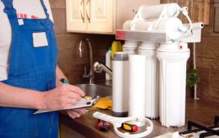
The main elements of an autonomous pumping station are a pump, a storage tank, a pressure switch for a hydraulic accumulator and check valve... The pressure unit pumps a given volume of water into the network. The hydroaccumulator accumulates and maintains a constant pressure to supply water to the consumer. The control unit ensures a stable cycle of operation of the equipment of the cold water supply system. Let's take a closer look at where it is applied and how to set up a hydraulic accumulator and pressure switch.

The water pressure switch regulates the switching on and off of the device supplying water to the hydraulic tank
Content
Hydroaccumulator in the cold water supply system
Direct connection of a submersible or surface pump causes unstable water supply. The pressure unit runs dry with minimal water consumption. The presence of a gravity or pneumatic accumulator in the system does not require constant operation of the primary pressure blower. The reserve tank maintains a constant consumption of water for household and drinking needs. The water supply reduces the dependence of the individual water supply on external factors.
The gravitational design of the accumulator is an atmospheric tank with a float level sensor. An open tank is installed in the attic of the house, above the water sampling points. The head in the system creates the weight of the liquid column. The pump is controlled by a float mechanism or level sensors.

Pumping station with a hydraulic accumulator and pressure switch
Modern hydraulic accumulators for autonomous water supply operate due to the excess pressure in the air chamber. The principle of operation of pneumatic accumulators is based on the interaction of compressed air and water. Pump pumps water into a rubber bulb, which is located inside the case. The volume of the air chamber decreases and the pressure increases. In the intervals between the switching on of the unit, the air pushes the water supply from the membrane into the consumer's network.
The water does not come into contact with the inner walls of the sealed container. An air chamber separates the membrane from the metal housing. If the accumulator is used in a drinking water supply system, then the membrane material is chemically neutral rubber. When using a storage tank in a heating or hot water supply system, membranes with high resistance to high temperatures are used.

Diaphragm tank design
There are vertical and horizontal models of pneumatic storage tanks of various capacities.The connection diagram of the accumulator determines the type of pump and the model of the accumulator. Horizontal tanks are used for remote surface units. The pressure blower is installed on the platform, in the upper part of the storage body (i.e. the cylinder is located below the self-priming pump).
Related article:
Rules for adjusting the water pressure switch for the pump. Having familiarized yourself with the simple rules for adjusting the water pressure switch, as well as the subtleties of setting, you can carry out such work yourself.
Pump stations with submersible units are equipped with vertical accumulators. The accumulator is located above the installation level of the submersible pump.
The volume of the hydropneumatic storage tank depends on the hourly water consumption, the power and frequency of pump activation, and the height of the pipeline system. The higher the water flow rate and the lower the pressure drop for turning the pump on / off, the larger the accumulator capacity.

Typical scheme of autonomous water supply from a well
Constructive elements of the accumulator:
- hermetically sealed metal casing designed to work under pressure (1.5 ÷ 6 atmospheres);
- elastic membrane - internal container for water supply;
- flange with valve for fastening the membrane to the body and filling it with water;
- nipple for pumping air into the air chamber of the cylinder;
- valve for venting air from the water chamber (for hydraulic accumulators with a volume exceeding 100 liters);
- bracket for mounting a small vessel on the wall or support legs, with mounting rubber pads for larger models;
- the set of the horizontal tank includes a support bracket for joint installation of a surface pump with a hydraulic accumulator and a pressure switch.
Important! The initial filling of the accumulator's hydraulic cylinder with water is carried out gradually, so as not to damage the integrity of the pear, because after storage, the walls of the rubber membrane usually stick together.

The pumping station will help to achieve a full-fledged autonomous water supply to the dacha
Calculation of the volume of the accumulator
The method for selecting a hydraulic accumulator is intended for individual houses that consume a large amount of water (sewerage, bath, shower, several mixers, bidet, washing machine and dishwasher). The total consumption coefficient and the maximum water consumption for household and drinking needs are determined by the number of water points. The volume of the accumulator is determined by the formula:
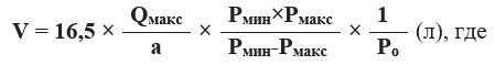
V is the volume of the accumulator, l;
Qmax is the maximum water consumption for household and drinking needs, l / min;
a is the number of system starts per hour (recommended value is 10 starts);
Рmin - pump activation pressure, atm;
Pmax - pump cut-off pressure, atm;
Ro is the pressure of the accumulator air chamber, atm.

The water supply structure consists of: 1 - hydraulic accumulator; 2 - pump; 3 - pressure switch; 4 check valves; 5 - power supply
A standard water supply installation for a small house with seasonal living, as a rule, is equipped with a hydraulic accumulator with a capacity of 24 liters. For a house with more than three parsing points, choose a 50 liter drive. Moreover, in the technical passport of the equipment, the manufacturer indicates the total volume of the cylinder (including the air chamber).
Adjusting the operating pressure of the accumulator
For domestic water supply of one-story houses, the pressure of one atmosphere is considered sufficient. However, it should be borne in mind that the air pressure in the air chamber must be greater than the static pressure of the highest tapping point.
The maximum shut-off pressure depends on the pump head characteristic. The pressure that the pump delivers divided by 10 corresponds to the upper response threshold for the automatic water supply system.The correction is made for linear hydraulic resistance, the real voltage of the electrical network, the technical condition of the equipment and the height of the water supply system at home.

Accessories for regulating the water pressure in the hydraulic tank
The recommended difference between the pressure on and off the pump for autonomous water supply is 1.0 ÷ 1.5 atmospheres. Increasing the factory setting (1.5 atmospheres) will decrease the reserve volume and increase the head in the system. High pressure of cold water supply increases consumption, leads to irrational use of energy resources.
Formula for calculating the required pressure in the accumulator:

Hmax - height in meters from the central line of the accumulator to the upper point of water withdrawal (for a two-storey private house 6 ÷ 7 meters).
The air pressure in the air chamber of the damper tank is checked and adjusted before installation, in case of settings failure or violation of the water supply operating mode. During the adjustment, the power of the pumping station is disconnected from the network, the water is drained from the accumulator.

All elements are fastened together using fittings
The pneumatic air chamber valve is located under the decorative cap on the tank body. Compliance or deviation of pressure from the specified operating parameters is determined using a pressure gauge connected to the spool. According to the measurement results, excess air is bleed off or the pressure of the air chamber is pumped up with a car pump.
If adjusting the operating parameters of the accumulator did not bring the desired result, then check the settings of the pressure switch.
Pressure switch device for a hydraulic accumulator
The pressure switch controls the operation of the pump and regulates the filling of the pneumohydraulic accumulator. The device integrates, controls and regulates the operation of the equipment of the cold water supply system.
The pump control unit looks like a small plastic box. The device is mounted at the entrance to the storage tank. The pressure switch for the accumulator consists of a mechanical and an electrical part.

Disassembled pressure switch
Elements of the standard design of the pressure switch:
- plastic case (cover with screws and base);
- metal membrane cover (with a nut for connection to the pipeline);
- rubber membrane;
- brass piston;
- two studs with threads and nuts;
- large and small adjusting springs;
- metal base plate;
- articulated platform;
- electrical contact assembly with flat spring;
- cable clamps;
- terminal block.

Pressure switch design and adjustment
The spring adjustment mechanism and the connection box are protected by a plastic cover. The metal base plate is supported underneath by a plastic case. The base separates the working body (diaphragm with piston) from the actuator (articulated platform, two adjusting springs on the studs and an electrical contact unit).
The electrical part of the water pressure switch is a two-contact relay for switching electrical circuits. The legs of the electrical contact assembly are sandwiched between the metal base plate and the plastic housing. Two clamps for clamping the cable (from the network and the pump power supply line) and the relay connection to the accumulator are located on the base of the plastic case.
Standard inlet diameter ¼ ”. From the side of the device, the inner section of the nut fastening to the adapter is limited by a rubber membrane. The reciprocating movement of the elastic membrane is communicated to the brass piston, which transfers the force to the articulated metal platform.

A pressure gauge is used to measure water pressure
Above, on the movable edge of the platform, a large and small spring are pressed against the force of the piston. The compression ratio of the large spring controls when the pump is turned on.The deformation range of the small spring ensures the shutdown of the pressure unit.
Ways to connect a pressure switch to a hydraulic accumulator
There are schemes for connecting a pressure switch to a hydraulic accumulator for water and electricity.
How to connect a water pressure switch?
The connecting branch pipe of the pressure switch of the accumulator pressure switch to the pipeline is rigidly fixed. The device is assembled assembled. Before starting assembly, ensure that there is sufficient space for the housing to rotate when mounting the pressure switch.
The device is screwed onto a thread cut into the pipeline separately or mounted directly on the outlet pipe of the accumulator through a special fitting. A five-way port allows a test gauge to be installed next to the pump control.

Connecting wires to pressure switch
How to connect a pressure switch to a hydraulic accumulator electrically?
Direct connection of the pressure switch is made from the 220V network, provided that the operating current of the pump does not exceed 10 Amperes.
Before connecting the cable, remove the protective plastic cover from the device. The electrical cable of the supply line or pump is led into a suitable socket. Outside, the wire is fixed with a nut with a crimp plastic ring. The designation of the contact groups is indicated on the body. The end of the cable is divided into cores. Phase, neutral, grounding stripped of the insulating braid and connected to the terminals of the contact group.
Important!Electrical installation and adjustment work is carried out with the equipment disconnected from the network. The electrical part is connected in compliance with the regulatory rules for technical operation and safety measures in electrical installations.

The relay automates the operation of the pumping station and turns off the water supply when the set point is reached
Rules for adjusting the pressure switch for a hydraulic accumulator
The relay controls the minimum and maximum pressure in the storage tank, maintains the pressure difference when the pump is turned on / off. The range of permissible setting values of the relay depends on the hourly flow rate and pump power.
The factory setting characteristics are indicated in the product data sheet. The standard value for the pressure switch setting for water supply systems is 1.0 ÷ 5.0 atmospheres. The starting pressure is 1.5 atmospheres. The range of the pump motor is 2.5 atmospheres. The maximum shutdown pressure of the unit is 5.0 atmospheres.
If the factory settings are not up-to-date or the installation has failed, then the setting and adjustment of the water pressure switch is carried out independently, using a manometer. The tester is installed on the accumulator manifold. The correction is made according to the readings of the pressure gauge after the pump is turned off. The pressure drop is created by opening the tap at the water take-off point closest to the accumulator.

Connecting a pressure switch and an automation unit to a submersible pump
The pressure switch of the accumulator is adjusted under pressure, without disconnecting the pumping station from the power supply. The pump must fill the storage tank and pressurize the network. When the relay activates and turns off the unit motor, it is necessary to remove the plastic housing cover and completely release the tension of the small spring mechanism.
How to adjust the water pressure switch to the minimum pressure for starting the pump?
Setting the large adjusting spring:
- the clamping nut is rotated clockwise to increase the starting pressure;
- loosening the tightness - reduces the pressure of the relay actuation and turning on the engine;
- to check the result of the adjustment, open the water tap and drain the water until the pump is turned on.

The pressure switch is adjusted using two nuts: large and small
How to adjust the accumulator pressure switch according to the pump shutdown pressure?
Setting the small adjusting spring:
- the nut on the pin of the small spring is tightened to increase the pressure difference;
- loosening the tightness allows you to lower the engine shutdown pressure;
- the result of the correction is checked by testing the pump.
If the pressure gauge reading matches the required value when the engine is turned on / off, the adjustment is complete. If it is impossible to adjust the operating device on their own, use the services of qualified specialists or buy a new device. If you decide to buy a pressure switch for a hydraulic accumulator, then pay attention to the compatibility of work with pumping equipment and the method of connecting the device to the power supply.

Automation with dry running protection based on four fittings
Important! An increase in the starting value of the factory setting of the pressure switch of the accumulator (above 1.5 atmospheres) creates a critical load on the diaphragm of the accumulator. The operating range of the pump is changed taking into account the maximum allowable pressure for the water fittings. The limiting pressure for which the sealing rings of mixers and taps are designed is 6 atmospheres.
The air pressure of the air chamber of the accumulator does not affect the operation of the pressure switch and the pumping station as a whole. Lack or lack of air leads to excessive stretching of the diaphragm and activation of the pump every time water is taken from the system. The increased overpressure of the air chamber reduces the volume of water in the membrane and the response interval of the pressure plant. Frequent switching on and off of the pump reduces the service life of the unit.
Normal operation of the pumping station is possible provided that the pressure of the air chamber of the accumulator is 10% lower than the pump activation pressure. Competent setting and adjustment of the pressure switch and the accumulator will ensure that the pump operates without overloads, and optimal filling of the storage tank with water. An integrated approach to setting up and adjusting equipment will extend the life of the membrane and increase the reliability of the autonomous water supply system.