Warm water floors in residential buildings and apartments serve as the main element of heat exchange in the room or complement the traditional radiator circuit. Wiring diagrams of water-heated floors in a private house are developed for individual design, repair or replacement of the heating system. The owner of the house independently chooses the type of heating devices.

Water underfloor heating is often used to heat a private house
Content
Wiring diagrams of water heated floors in a private house
Wiring diagrams of water heated floors are developed in accordance with the calculated heat consumption and its losses through the enclosing structures. Features and rules for calculating a water-heated floor were given earlier in the article "Calculation of heat underfloor heating". When starting to independently develop wiring diagrams, you need to remember:
- the total thermal load of a room depends on the degree of insulation, thickness and material of walls, floors (floors, ceilings), window and door openings. The calculation is made taking into account the climatic zone of the area of residence. If the calculated value of heat transfer exceeds 100 W / m², then using warm water floors as the main heating option is unprofitable;

3D-scheme of arrangement of a water-heated floor in a private house
- underfloor heating system consists of parallel functioning circuits. The length of one heating circuit depends on the heat load, the usable area of the room, the method and pitch of the pipe laying;
- the building area of the premises does not coincide with the area occupied by the floor heating circuit. The usable area takes into account the free space, which does not include the installation places of built-in furniture and the indentation from the internal (0.3 m) and external (0.1 ÷ 0.15 m) walls;
- premises with a usable area of more than 30 m² are divided into sectors. Each section is heated by an independent circuit connected to a distribution manifold. The length, pitch and diameter of the links connected to the manifolds of the same valve must be equal. An exception is made for areas of contour reinforcement along the outer walls;
- water floors are an element of a volatile heating system. The long length and complex configuration of the low temperature circuit requires the installation of a common or several circulation pumps. The preset pressure in the heating system of a small house can be maintained by a boiler with a built-in pressure blower. Installation of circulation pumps and control valves in each circuit is necessary to balance the underfloor heating of a large house (over 150 m²);

Various options for laying pipes for a warm floor
- installation schemes for a warm water floor (simple, angular, double loop or spiral) depend on the heating method and the geometry of the room.Additional heating allows simple single loops, with a step of 0.2 ÷ 0.3 m. The main heating with warm water floors is arranged with double loops or spirals (step 0.1 ÷ 0.15 m);
- the pitch and length of the individual chains determines the diameter of the selected pipe. The larger the internal cross-section of the pipe, the greater the permitted loop length. The distance between the axes of the supply and return pipes must maintain optimal thermal conditions. The standard indicator for the temperature difference in neighboring areas is 5 ° С;
- the height of the underfloor heating pie is taken into account when decorating door and window openings, installing fasteners for heating devices. The passage of pipes through the doorway is performed in a metal casing. Places of pipe laying are fixed in a certain position so as not to damage the liner when installing the door block.

The process of installing a water-heated floor
Installation technology for a warm water floor
The technology of installation of warm water floors is distinguished by the principle of the base arrangement of the heating circuit. The basis for warm water floors is chosen taking into account the bearing capacity of the interfloor overlap and the intended floor covering. Watching a video of installation diagrams of warm water floors in a private house will help you get a clear idea of the sequence of operations and the technology for performing work.
Experts call warm water floors floating. A damper tape 12 ÷ 18 cm wide is mounted around the perimeter of the room and each circuit, if the room is divided into independent sectors. The edge film along the height of the screed acts as an expansion joint. The shock absorber ensures the safety of the floor covering and the heating circuit during thermal expansion, vibration and movement of building structures. The tape reduces heat loss at the joints between the heating plate and the outer walls.

Installation scheme for underfloor heating for rooms on the first floor of a private house
On concrete slabs, warm water floors are arranged in a bulk cement screed. The concrete base is lined with waterproofing, a layer of insulation and reinforcing mesh are laid. Pipes are attached to the cells of the frame using clamps, special clamps or steel wire. On top of the pipe loop, to evenly distribute the operating load of the floor covering, if necessary, a reinforced screed is also arranged.
A lightweight base that combines the functions of insulation and a frame - folding or special profile mats made of extruded polystyrene foam. In the first case, the pipe on the surface of the substrate is fixed with special clamps with harpoon tips or mounting rails. On the profile mats, the contour loops tightly fix the bosses, no additional fasteners are required. An improved version of the profile mats is covered with a waterproofing layer and equipped with a system of locking protrusions.

Laying scheme for a water-heated floor in "dry" rooms on the second floor
Important! Installation of a polystyrene system requires care. The prefabricated screed for the floor covering is performed immediately after the pipes are laid. The surface of the elements made of foamed plastic withstands well distributed loads, but it is easily punched out under the heel or a fallen instrument.
Modular systems made of wood or wood composite are laid on the sub-floor. Wooden rack-and-pinion systems are formed along the logs. The pivoting and straight grooves of wood flooring systems are designed for laying heat distribution plates made of galvanized steel or aluminum.
Pipes that are used to lay out a warm water floor (cross-linked polyethylene, metal-plastic, copper, corrugated corrugated stainless steel with an internal polymer coating, less often polypropylene) are produced using seamless technology. The contour is laid out from a solid pipe. Butt joint with standard fittings in the screed body is permissible only for circuits made of corrugated pipes.The surface of the pipes must be resistant to oxygen corrosion, have a margin of temperature and mechanical strength, and have a smooth inner surface.

Wiring diagram of a water heat-insulated floor in the "wet" rooms of the second floor
Coils of pipes for underfloor heating are not opened in advance - careless handling can lead to the formation of creases. Installation starts from the supply manifold comb. Gradually unwind the coil, carry out the intended layout, and return the solid pipe to the distributor. The circuit is connected to the paired nozzles of the manifold combs.
After the installation of all floor heating circuits, the system is checked for strength and tightness of the connections. After testing and a successful test run, the cement screed is poured. The final floor covering is mounted after the screed has completely dried.
Wiring diagrams for connecting a warm water floor to a heat source
An autonomous heat generator in a private house heats water up to 95 ° C. The optimum temperature difference between supply and return is 20 ° C. However, the maximum allowable temperature coolant in the underfloor heating system - 55 ° C, heat removal 5 ° C. In practice, the operating range of the floor circuit coolant does not exceed 40 ÷ 35 ° C.

Heating scheme for a two-story house with automatic temperature control in the premises: 1A - pipe 16 mm; 1B - pipe 26 mm; 2 - ball valve; 3 - direct-flow valve; 4 - membrane tank 24 l; 5 - circulation pump; 6 - check valve; 7 - security group; 8 - collector block; 9 - electrothermal servo drive; 10 - electronic thermostat; 11 - distribution cabinet; 12 - connector; 13 - self-sealing plug; 14 - nipple; 15 - crimp connector; 16 - corrugated casing; 17 - ball valve
The temperature is controlled by means of forced mixing of flows: part of the coolant from the return flow enters the supply pipeline. Mixing units are installed between the boiler and the distribution manifold.
There are models of gas appliances that have a built-in underfloor heating circuit: in the "underfloor heating" operating mode, the automatic system limits the flow temperature at the boiler outlet to 45 ° C. The operation of a conventional gas boiler in underfloor heating mode reduces the efficiency of the unit.
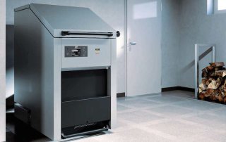
Solid fuel boilers for long burning on wood are distinguished by a complex adjustment of the combustion mode. The installation of underfloor heating in heating systems with a solid fuel heat generator, in addition to a circulation pump, requires the installation of a buffer tank. The heating medium is taken directly from the hydraulic accumulator to the underfloor heating system.

Connection diagram of warm water floors to solid fuel boiler
Electric boilers are the most profitable and acceptable option for the efficient operation of underfloor heating. Automation of electrode, induction or units with a tubular electric heater is able to maintain the specified temperature of the coolant without losing the heat output of the boiler. Underfloor heating of small houses (up to 100m2) allows direct connection of circuits to an electric boiler. Warm floors of large private houses are arranged using a coplanar distribution comb and a mixing unit.
Related article:
Do-it-yourself water floor heating, video and description of the process. The nuances of installation. Description of the process of installing a water-heated floor. Its advantages and disadvantages in contrast to other types.
Wiring diagrams of warm water floors in the apartment
The main or additional low-temperature circuit of underfloor heating from central heating in apartment buildings is planned during the development of the project. It is prohibited by housing legislation to independently make changes to the radiator heating scheme of an apartment building. The temperature of the radiator circuit is higher than the required parameters for underfloor heating.An unauthorized change in the direction, diameter and length of a common house heating riser leads to an imbalance in the system and a violation of the thermal regime in a residential building.
Specialized organizations install underfloor heating from central heating in apartments during the construction of a building. The principle of underfloor heating device differs from central heating in an apartment by the way of connecting low-temperature circuits. The coolant enters the pipes of the water-heated floors in a separate riser from the radiator heating. Hot water for underfloor heating is prepared by a heat exchanger, which is installed in a central heating point, a heating unit of an apartment building or directly in a consumer's apartment.

Diagram of inserting warm water floors into the radiator circuit of central heating: 1 - ball valve on the inset of the supply line; 2 - ball valve on the return line tie-in; 3 - mesh filter; 4 - check valve; 5 - three-way mixing valve; 6 - bypass valve; 7 - circulation pump; 8 - valve at the outlet of the return manifold; 9 - shut-off valve at the inlet of the supply manifold; 10 - return manifold; 11 - supply manifold housing; 12 - ball valves on the return line of the circuit; 13 - ball valves on the supply of the circuit; 14 - air vent valve; 15 - drain valve; 16 - radiator
Theoretically, the last consumers (in the direction of movement of the coolant in the riser) can change the length of pipes without affecting the thermal regime in neighboring apartments. If the heat is distributed from above, then the warm floor on the ground floor does not affect the heat exchange of the apartments located above. However, the operating pressure of the supply line in the lower permanent wiring may not be enough to circulate in the floor circuit of the upper floor.
In the absence of initial design data for the underfloor heating device in an apartment building, the connection of an additional circuit is coordinated with the heat supplier and the management company. Resource supplying organizations issue a permit for the installation of warm semi-autonomous floors, with a sufficient power reserve of the existing heating system.

Combined heating in the apartment using radiators and water floor heating
Housing maintenance companies make a prerequisite for the design load of the bases of underfloor heating, which should not exceed the permissible load on interfloor floors in this particular case.
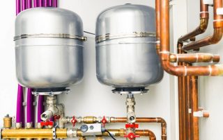
Traditionally, approval provides for the installation of a heat exchanger on a radiator or hot water riser in an apartment. This requires the installation of a circulation pump, expansion tank, safety group, valve for air removal, two-way valve, control valves and heat meter.
; 6 - bypass valve; 7 - circulation pump; 8 - valve at the outlet of the return manifold; 9 - shut-off valve at the inlet of the supply manifold; 10 - return manifold; 11 - supply manifold housing; 12 - ball valves on the return line of the circuit; 13 - ball valves on the supply of the circuit; 14 - air vent valve; 15 - drain valve; 16 - heat exchanger; 17 - security group; 18 - thermometer; 19 - control valves; 20 - bypass between the supply and return collectors; 21 - expansion tank of membrane type")
Semi-autonomous scheme for connecting warm water floors in an apartment: 1 - ball valve in the tie-in into the supply riser; 2 - ball valve on the bypass to the return riser; 3 - mesh filter; 4 - check valve; 5 - two-way valve (temperature sensor with a servo drive); 6 - bypass valve; 7 - circulation pump; 8 - valve at the outlet of the return manifold; 9 - shut-off valve at the inlet of the supply manifold; 10 - return manifold; 11 - supply manifold housing; 12 - ball valves on the return line of the circuit; 13 - ball valves on the supply of the circuit; 14 - air vent valve; 15 - drain valve; 16 - heat exchanger; 17 - security group; 18 - thermometer; 19 - control valves; 20 - bypass between the supply and return collectors; 21 - expansion tank of membrane type
For multiple floor contours, a ready-made manifold assembly is used that is compatible with any flooring scheme. A shut-off valve or thermostat must be installed at each inlet and outlet of the manifold manifold. Shut-off valves make it possible to switch off a separate circuit without disturbing the overall operation of the underfloor heating.
Particular attention is paid to the choice of underfloor heating in old houses.The transverse size of the cement screed depends on the degree of insulation floor slabs... The thickness of the "pie" of warm floors over a cold basement reaches 0.15 m, which significantly hides the overall height of the room and increases the weight of the structure.

Rough screed process warm floor under the tiles or other DIY coating
Helpful advice! A reasonable solution would be to opt for a lightweight base for water-heated floors using heat transfer plates made of stainless steel or aluminum.
The cost of installing warm water floors
The total price of installing a warm water floor includes the funds spent on the purchase of material, calculations, preparatory work, installation, connection and hydraulic testing of the circuits for strength and tightness of the connections.
The services of hired specialists will cost 1,500 ÷ 2,500 rubles per 1 m² of heated floor. The total amount depends on the number of circuits, type of foundation, cost of pipes, manifold group and pumping and mixing unit. Do-it-yourself installation of warm water floors allows you to reduce the cost.

Components for the installation of a heating system "warm floor": 1 - cross-linked polyethylene pipe, 2 - heat-insulating mats, 3 - pipe fastening brackets, 4 - damper tape, 5 - collector, 6 - collector cabinet, 7 - wall thermostat, 8 - plasticizer
Important! The quality of the material, equipment, shut-off and control valves must correspond to the purpose of the system and the terms of its intended service. It is profitable to purchase ready-made sets of underfloor heating, which are equipped with high-quality and compatible equipment and materials. Free calculation of warm water floors with a batch purchase is an additional bonus from large manufacturers.
The videos of the installation of a water-heated floor with your own hands posted on the Internet, with explanations from the authors, will help you better understand the essence of the issue. Detailed descriptions of the methods of arrangement and the choice of material for warm floors will help if there is an urgent need for underfloor heating, but there is no possibility of hiring specialists.