From this article you can learn how to make a metal cutting machine with your own hands at home using the simplest materials. Here are detailed all the stages of creating structures, which are based on a cutting disc or grinder: preparation of materials and tools, calculation formulas, detailed step-by-step instructions, as well as related information with useful tips.
Content
- 1 DIY metal cutting machine: recommendations for creating
- 1.1 Making a disk cutting machine for metal with your own hands: procedure
- 1.2 Calculation of a pulley for a homemade metal cutting machine
- 1.3 Do-it-yourself belt length calculation for a homemade metal cutting machine
- 1.4 Principles of creating a machine for cutting metal
- 1.5 Assembling a metal frame for a cutting machine
- 1.6 Assembling the electrical component for the machine
- 2 Making a cutting machine from a grinder with your own hands: drawings, technology
DIY metal cutting machine: recommendations for creating
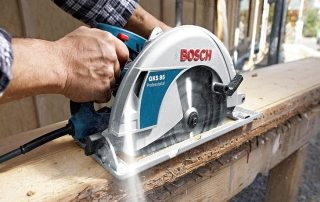
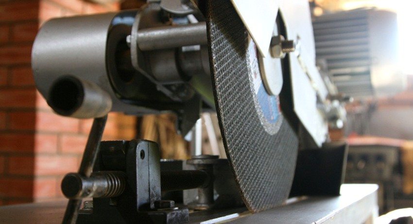
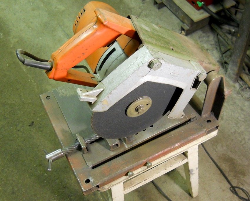
Disc saws are tools based on a special platform or frame made of metal. The machine itself is equipped with parts that ensure reliable fixation of the material in a certain position at the required angle during its cutting.
A disc made of high speed steel is used as a cutting element in such structures. It is also called carbide. It can also be used for cutting metal with a coated abrasive disc. The cutting element is driven by an electric motor with a belt or gear drive.
Note! In low-power versions of the tool, it is allowed to use a cutting element installed directly on the shaft of an electric motor. In other cases, such use of the disc can be dangerous.
There are three different cutting component feeds for disc machines:
- bottom;
- pendulum;
- frontal.
By the number of cutting elements, machines are:
- single-head - only one cutting disc is included in the package of the device, therefore, if it is necessary to replace the operation, the cutting edge is readjusted in accordance with the new task;
- double-headed - the design makes it possible to work with two tools at once, thereby increasing the efficiency.In such machines, one head is in a fixed position and maintains stability, the second head can move. Two-head structures can work automatically.
Making a disk cutting machine for metal with your own hands: procedure
In the manufacture of a machine designed for working with metal, the actions are performed in the following order:
- Protective covers are being prepared, which will be installed on the drive belt, as well as the cutting disc.
- The motor is installed. A drive belt acts as a connecting piece between the cutting element shaft and the motor.
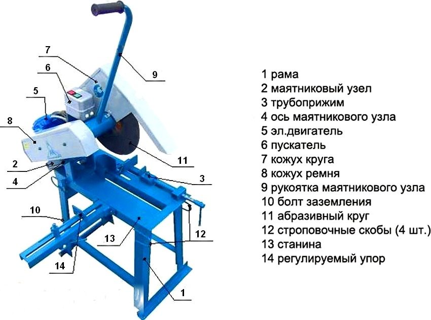
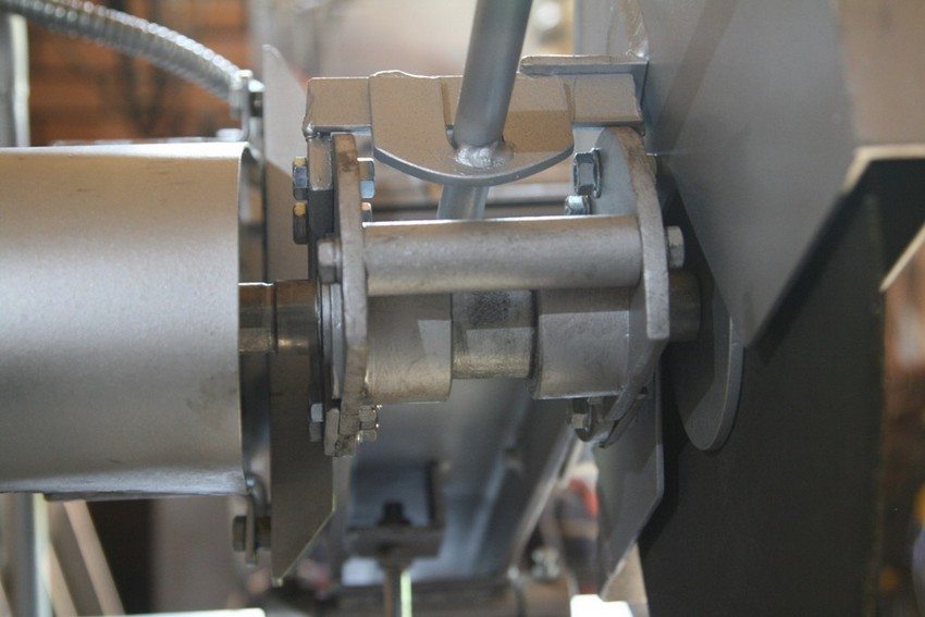
- A shaft is made, on which the drive pulley will be fixed, and the cutting disc will also be installed. The unit is subject to assembly and subsequent installation on a pendulum. In this case, the movable upper part of the structure acts as a pendulum, where the cutting element and the motor are located.
- A shaft is made for attaching the pendulum.
- A frame for installing the machine is being made. The spark arrester and the workpiece will be fixed on it.
- The pendulum is mounted on the frame.
- Electrical wiring is being installed.
- A trial run of the tool and equipment adjustment are carried out.
Calculation of a pulley for a homemade metal cutting machine
The calculation of the pulley diameter is carried out taking into account the rotational speed of the disk and other parameters. If we assume that the engine power will be at least 300 W, the rotational speed of the disk will be at least 3000 rpm, and its size will be 40 cm in diameter.
Useful advice! In the process of cutting metal, the nut in the disk fixation zone can be unscrewed. To avoid this, it is recommended to place the drive pulleys on the left side, and the disc itself on the shaft - on the right.
Usually the discs are marked by the manufacturer, who applies the maximum allowable rotational speed to the product. In this case, the figure is 4400 rpm. Therefore, it is allowed to select any speed in the range of 3000-4400 rpm.
Calculation data:
- rotational speed of the motor - 1500 rpm;
- the diameter of the pulley intended for installation on the shaft is 6.5 cm;
- rotational speed of the disk - 3000 rpm.
The calculation is performed in the following sequence:
- We set the length of the shaft around the perimeter. To do this, the number π, which is 3.14, is multiplied by the size of the diameter: 3.14 x 6.5 = 20.41 cm (the length of the shaft around the perimeter).
- The resulting value is multiplied by the required number of revolutions: 20.41 x 3000 rpm. = 61230 cm / min.
- The result must be divided by the number of engine revolutions: 61230 cm / min / 1500 rpm. = 40.82 cm (circumferential motor pulley length).
- The resulting value is divided by the number π: 40.82 cm / 3.14 = 13 cm (required pulley size).
Do-it-yourself belt length calculation for a homemade metal cutting machine
To perform these calculations, the following data is required:
- drive pulley parameters (radius);
- distance separating the center points of the pulleys;
- parameters of the driven pulley (radius).
Having 2 pulleys with dimensions of 13 cm and 6.5 cm, you can make the necessary calculations. Since the distance between the centers of these elements lends itself to change (since it is required to bring the belt into tension), a 50 cm segment will be taken as an example.
Now you need to count 1/2 the circumference of each of the pulleys. Since the drive belt runs between them twice, double the distance between the center points must be added to this value.
First pulley (circumference):
3.14 (number π) x 3.25 cm = 10.20 cm
Second pulley (circumference):
3.14 (number π) x 6.5 cm = 20.41 cm
Drive belt (required length):
20.41 cm + 10.20 cm + 50 cm x 2 = 13.06 cm
Useful advice! To get a more accurate result, you should make calculations with the maximum and minimum distance between the center points of the pulleys and choose the average value.
In order to independently make the structure of a machine for working with metal, you should prepare the necessary tools.
A mandatory set of tools and materials includes:
- welding machine;
- metal corner (steel);
- channel and chain;
- button to turn on / off;
- bearings;
- shaft and electric motor;
- electric drill;
- sheet steel to create a work surface;
- box for placing the electrical components of the machine.
Principles of creating a machine for cutting metal
The scheme for making a home-made machine tool obeys certain principles, they must be taken into account before getting down to business:
- it is very important to choose the right gear and install it. The safety of the torque and its correct transmission from the engine to the cutting element (disk) depend on this component;
- it is imperative to provide for vice... This tool contributes to more comfortable work, and also increases the degree of its safety;
- selection of the optimal cutting angle. The allowed range is 45-90 °. In most cases, experts prefer right angle cutting;
- the diameter of the cutting disc is selected taking into account what materials the master will work with in the future on this machine. The larger the diameter of the cutting element, the easier it will be to cope with cutting thick metal;
- when designing and drawing up drawings, such indicators as the dimensions of the future machine and its weight must be taken into account. These values are directly influenced by the materials from which the equipment will be made. The layout of the parts is also important.
Note! When drawing up drawings, special attention should be paid to vibration mountings, which are installed on the legs.
Assembling a metal frame for a cutting machine
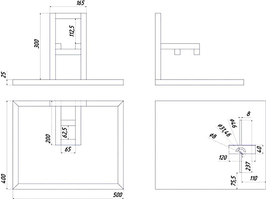
After all the tools are prepared and the drawings are selected, you can go directly to the process of creating a machine. Using steel corner, it is necessary to make the frame part of the structure. In accordance with the drawings, which can be drawn up independently or found on the network, the elements of the frame are cut out. All of them are connected to each other by welding. First you need to check the compliance of the sizes.
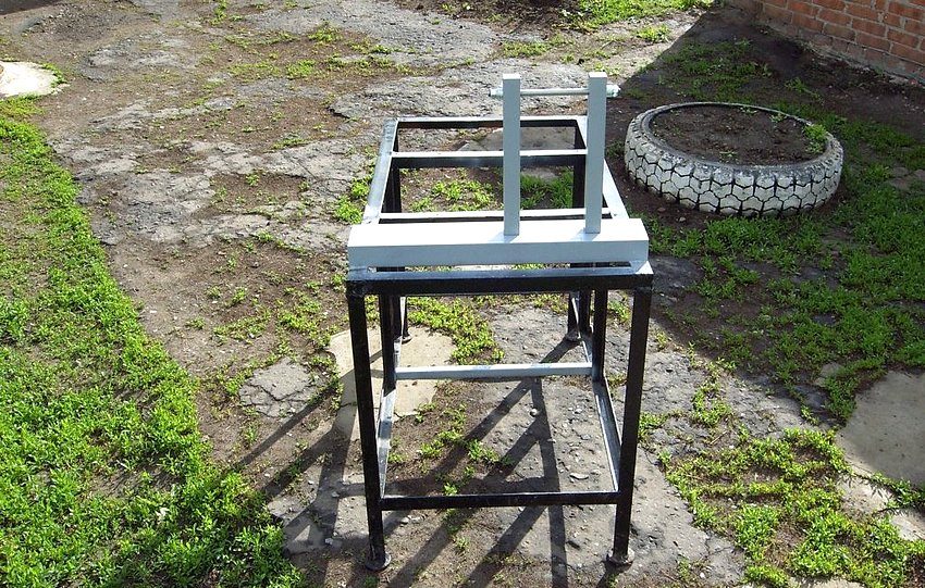
A channel is welded to the upper part of the frame - it will become a guiding element and will serve as the basis for further installation of the cutting component on the machine. This channel will become a kind of connecting link between the electric motor and the cutting element. After that, vertically located racks are fixed on it with bolts.
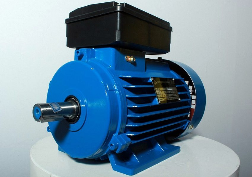
You will need to weld the structure of another frame. Dimensional parameters are selected individually, taking into account the dimensions of the electric motor and its features. When choosing an electric motor for a machine tool, it is better to pay attention to modifications of the asynchronous type. This type of equipment is characterized by increased reliability and durability.
There is one subtlety when choosing a motor. The more powerful the engine, the smoother the disc will travel.
Assembling the electrical component for the machine
The installation of equipment involves the installation and connection of the working shaft to the electric motor of the machine. The way in which this can be done is not critical. If the drawings contain instructions for performing this procedure, it is better to follow it, since the correct operation and reliability of the tool depends on the quality of the installation.
Useful advice! Some parts that you cannot make on your own can be ordered from a turner. These include the fixing flanges as well as the pulley.
It is better to use a bolted connection with nuts to secure the motor to a metal frame. It is recommended to locate a box near the engine where the switch and electrical circuit are located, as well as a remote control for controlling the tool.
The channel, designed to fix the cutting disc, is best placed on a spring. It is necessary to make sure that when released, it returns to its original place. You can use bolts and a clamp to secure the spring.
The electrical component is the most important part of the instrument. Be sure to include in the design a chain for starting, as well as a button for emergency shutdown of the machine. It is necessary to achieve such an arrangement of parts in which the electric motor will be connected to electricity through an automatic machine and a box, and not directly. A three-lane starter will be enough to turn on and fully start the engine. It will also power the shutdown button.
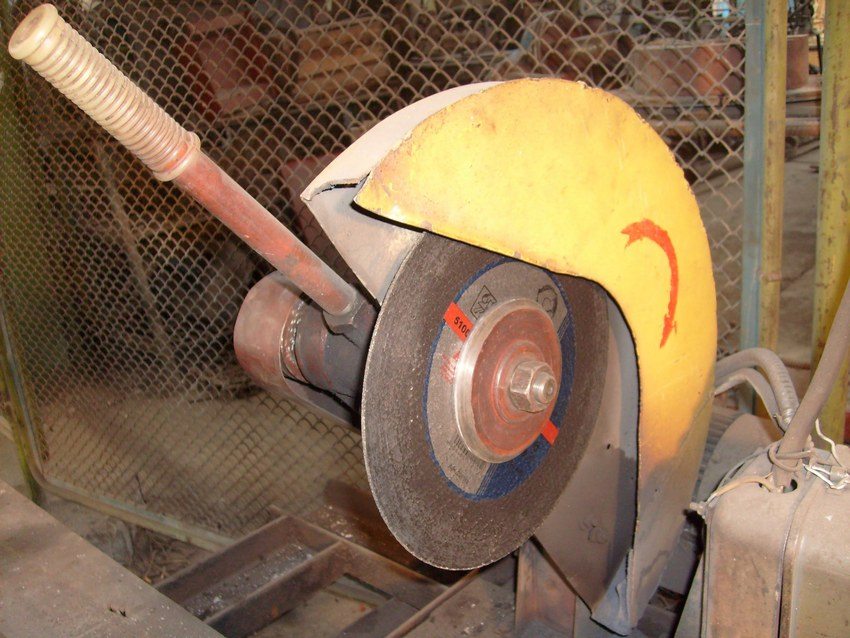
Finally, it is worth taking care of the availability of protective devices that will protect a person during work. To do this, you need to make a protective cover. It will prevent sparks and small metal particles from entering your eyes.
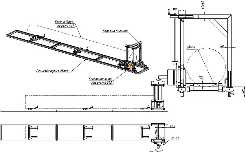
Making a cutting machine from a grinder with your own hands: drawings, technology
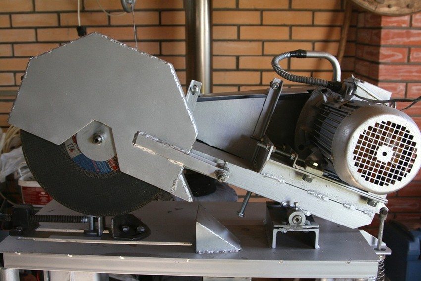
The designs of cutting machines made on the basis of the grinder are of two types (depending on the location of the grinder).
In the first case, a frame is obtained on which an angle grinder is very rigidly fixed. Only the disk rises above the working surface, for which there is a special slot in the table. Such a machine operates on the principle of a circular saw.
Note! In the process of working with such a machine, you have to independently move the workpiece, which is why the accuracy of the work is lost. In addition, this process can be unsafe, therefore, drawings with a hidden type of grinder placement are not in high demand.
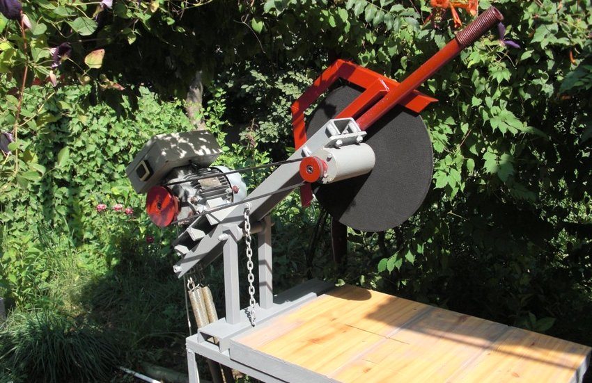
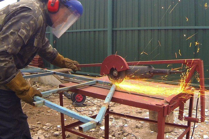
The second option assumes that the workpiece remains stationary and the cutting element moves. Because the sander is positioned on top of the table top, no major effort is required to cut parts.
List of tools and materials for a do-it-yourself grinder cutting machine
When making a tool yourself, it should be borne in mind that the accuracy with which it will work depends largely on the stability of the structure. For this reason, the thickness of materials for manufacturing is associated not so much with the requirements for the strength of the machine body part, but with the need to ensure the proper level of rigidity.
List of materials:
- profiled pipe with a square section (2.5x2.5x0.25 cm);
- sheet steel (sheet thickness 0.4-0.5 cm);
- profiled pipe with rectangular section (4x2x0.25 cm);
- ball bearings - 2 pcs. (# 203, 204 or 202);
- calibrated bar no more than 10 cm (thickness is selected taking into account the hole in the inner bearing race);
- metal bar (diameter 0.8-1 cm);
- fasteners (bolts with nuts, thread M or M8);
- metal tire (2x0.4 cm).
List of tools:
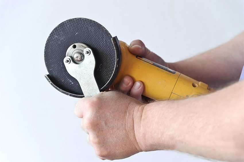
- angle grinder;
- electric drill (can be replaced with a drilling machine);
- set drills;
- a set of dies designed to form a metal thread;
- welding machine;
- carob keys.
Choosing the right cutting tool for a homemade cutting machine from a grinder
The angle grinder is the main component of the metal working machine. Experts do not recommend using a small tool for these purposes, which has a power of no more than 500-600 W. In such grinders, cutting discs have a diameter of no more than 12.5 cm. These restrictions are due to the fact that a cutting element with a large diameter is considered versatile and very reliable - it is able to cope with cutting thick workpieces.
Useful advice! Instead of welding, threaded joints can be used to fix parts, but they are less reliable and cannot provide the required level of strength.
It is also necessary to carefully approach the choice of a grinder because there is a wide variety of designs on the market. Since this power tool is not completely unified, the construction of the machine will be carried out under a certain modification and dimensions of the angle grinder.
If the machine breaks down, installing another grinder can be not only problematic, but also impossible. We'll have to redo the pendulum and all the mountings. Therefore, it is worth choosing a tool from an assortment of large and already proven companies, for example, Bosch or Makita.
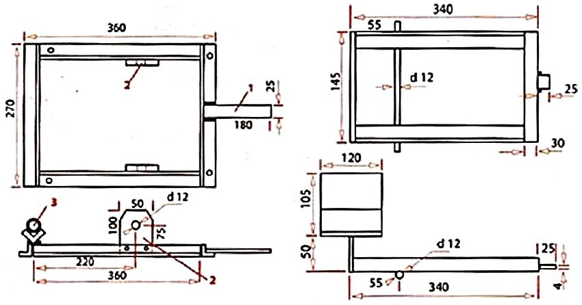
Cutting machine drawings: how to make a cutting tool from a grinder
At the preparatory stage, design and drawing up of drawings is carried out. There are no uniform dimensions for the reason that the design of each machine is subject to a specific cutting tool model. Ready-made drawings, of which there are many on the network, can be adjusted to fit the grinder. They allow you to navigate in relation to what the structure of the structure will be, its dimensions.
It is better to start drawing up a drawing with the body part. In some cases, it may be necessary to build a separate platform instead of a frame. Such a platform will be fixed on a locksmith's workbench. Next, the dimensions and nature of the arrangement of the nodal elements on the machine are determined. It is necessary to measure the center-to-center distances between the mounting holes located on the gearbox, and also measure the grinder itself.
All this data is used to draw up drawings. After the pendulum and grinder mounts have been designed, the pivot assembly is designed.
Useful advice! The accuracy and rigidity of the machine depends on the distance between the cutting element and the swivel joint. The smaller the gap, the better. It is recommended to install a pendulum with a minimum length.
After drawing up the drawings, it remains only to pick up the materials, calculate their quantity and proceed with the construction.
Technology of creating a cutting machine from a grinder
The manufacturing technology of a machine for cutting metal based on a grinder is practically the same as in the case of cutting disc:
- Preparation and manufacture of parts for the frame.
- Arrangement of a swivel joint on a pendulum arm.
- Manufacturing of a U-shaped bracket with holes for mounting a grinding machine gearbox.
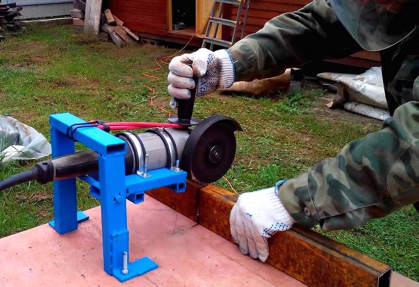
- Making a U-clamp and a strip that will fix the grinder body on the pendulum.
- Mounting the U-clamp and the U-bracket to the cutting tool: by welding or screwing, all these parts are attached to the console part.
- Pressing bearings into supports.
- Double-sided pressing of bearing assemblies onto the shaft. To increase the strength of the connection, you can tin the axle with a thin layer of tin using a soldering iron.
- Fastening a pendulum with supporting knot parts at the edge of the platform (distance from the edge 0.5-0.6 cm) using a welding machine.
- Installation of a grinder and a protective casing.
- Installation of the return spring.
After the structure is assembled, it is necessary to perform a test run and check the correct operation of the equipment, as well as the placement of all parts on it. At the final stage, the groove is adjusted to the cutting element, the supports are installed, designed to fix the workpieces.
When the finishing is completed, the machine body must be covered with a thin layer of enamel. Painting will protect the tool from damage that rust can cause.