The dacha today is no longer a summer building with amenities in the yard, but in fact a full-fledged suburban housing. Moreover, equipped with powerful modern technology - refrigerator, washing machine, microwave oven. All of these mechanisms make housework easier, but they are also objects of increased danger. In order to avoid fires and tragic accidents, it is recommended to equip grounding in the country with your own hands. The circuit diagram is not so complicated, and it is not necessary to invite specialists for installation.

Do-it-yourself installation of a grounding loop in the country
The most common grounding system is the design of three metal rods (electrodes). The rods are buried in the ground and welded together with a horizontal steel strip. The finished ground loop is connected to the power shield using a steel rod laid underground.
Helpful advice! It is not recommended to mount the ground loop in rocky and stony soils - the specific resistance of the rock is too high.

Elements of the grounding system at the summer cottage
Content
The principle of the grounding system
Residential buildings are usually powered by a single-phase 220 volt alternating current. The operation of household mechanisms and installations is provided by an electrical circuit in which there are two conductors - a phase and a neutral wire.
The design of each electrical appliance provides for the presence of insulation and fuses that protect a person from electric shock. Imagine a situation where unreliable contacts sparkle. In this case, the voltage will fall on the body, for example, of a washing machine. The hostess, touching her faithful assistant with a wet hand, will receive a strong electric shock.

The principle of the grounding system
It is especially dangerous when next to the faulty unit are metal structures with so-called. natural grounding. These include:
- heating pipes and radiators,
- water pipes,
- gas pipes,
- open reinforcement of reinforced concrete slabs.
; 2 - horizontal earthing switch (steel 40x4); 3 - vertical earthing switch (a - pipe 50x3, b - round steel, c - corner 50x50x5); 4 - grounding conductor; 5 - copper or aluminum ground wire; 6-welded seam")
Ground loop diagram: 1 - fastening (bolt М6, М8); 2 - horizontal earthing switch (steel 40x4); 3 - vertical earthing switch (a - pipe 50x3, b - round steel, c - corner 50x50x5); 4 - grounding conductor; 5 - copper or aluminum ground wire; 6-welded seam
Grasping at the same time battery and for the body of the machine, the person closes the electrical circuit on himself. The current will go towards zero potential (to the ground), including through the body. The nature of electricity is such that the flow of electrons, like the flow of water, moves through the channels with the least resistance.
To protect households from such accidents, they mount a ground loop in the country with their own hands. Whether the circuit of the device fails, or the insulation breaks through with a discharge, trouble will not happen. A pre-created grounding line will divert hazardous voltage to a point of minimum resistance, namely to the ground.

DIY grounding device
Invalid grounding schemes
Some DIYers are convinced that water pipes and heating pipes can be used to drain the current. Such grounding in the country with your own hands cannot be called a safety scheme. Pipes are highly oxidized or have poor ground contact. In addition, plastic connections are often included in the piping system that open the electrical circuit.
Many modern electrical appliances are equipped with a cable with a three-wire plug. The same sockets are installed to them. The neutral wire in the cable is indicated in blue, the grounding wire is yellow-green, the phase is any other than those mentioned.

Organization of grounding in the country kitchen: 1 - electric stove, 2 - ground wire
Wanting to save money on a do-it-yourself grounding device in the country, the scheme is used as follows: a jumper is made in the outlet between the grounding and zero contact. However, such a project is extremely unpredictable. If a reverse phase or poor contact of the working zero occurs in any part of the circuit, a dangerous voltage will appear on the instrument case.
Some homeowners, by installing a special protective device (RCD), consider the problem solved. But the operation of the RCD will be correct only if there is grounding. Then, with a leakage of current, the electrical circuit will immediately close, and the mechanism will work, turning off the power to the dangerous area.

Schematic representation of a grounding device in a private house
Do-it-yourself grounding in the country. Contour diagram
The resistance of the current drainage system must be less than the resistance of the human body. For calculations, the average value is taken - less than 4 ohms. In the standards, there are values of permissible resistance of 0.5 Ohm, 30 Ohm, 60 Ohm. But here, where it is actually a matter of life and death, less is better than more.
Related article:
|

Soil resistance
The grounding circuit should provide the lowest possible resistance and reliable contact with the ground. However, the soil has different resistivity. It depends on its composition:
- sand - 1000 Ohm * m;
- black soil - 200 Ohm * m;
- sandy loam - 150 Ohm * m;
- loess loam - 100 Ohm * m;
- semi-solid clay - 50 Ohm * m;
- plastic loam - 30 Ohm * m;
- peat or plastic clay - 20 Ohm * m.

Resistivity indicators of different soil layers
We see that the layers with the lowest resistance values are located at a considerable depth. The problem of successful grounding is solved in several ways:
- deeper immersion of electrodes in the soil;
- adding additional vertical elements;
- increasing the contact area of the rods with the ground (using wider pins with a large cross section);
- increasing the distance between the electrodes.

Installing a socket with grounding contacts
Basic grounding schemes in country houses
- Recessed metal contour around the building. Basically, these are fittings driven into the ground. The rods are interconnected by a welded metal bus.
- The most popular do-it-yourself grounding system in the country is a diagram of three or more long electrodes immersed in the ground, connected by a steel strip.
- Earthing with one rod recessed to a considerable depth (from 6 meters).
- Foundation earthing switch. It is a closed loop made of welded metal mesh. It is laid under the bottom waterproofing layer of the foundation, or along the bottom row of fittings. Such grounding can only be installed when pouring the foundation.
Helpful advice! Metal elements that act as electrodes must not be painted. This impairs their conductivity.

A steel strip 40-50 mm wide is used for strapping the grounding loop
DIY earthing system installation
For a detailed consideration, let's take the grounding system in the country with our own hands, scheme number 2 - a triangle with pins at the tops.
Material for electrodes:
- steel corner with a minimum width of 4 × 4;
- reinforcing bar with a section of 10-12 mm;
- metal pipe with a wall section of 3.0-5.0 mm;
- steel strip 50 mm wide.
Helpful advice! The fittings must be smooth. The corrugated surface does not provide a solid contact of the electrode with the ground. Driving creates voids that reduce the quality of grounding.

DIY grounding contour in a summer cottage
The length of the pins should be approximately 3 m. A metal strip with a cross section of 4 × 40 mm or reinforcement with a diameter of 14 mm can be used as a strapping. When connecting the contour, welding is necessarily used.
Work order
First, select and clear a place in the area where the contour will be installed. It is optimal if the distance from the electrodes to the power cabinet is about 10 m. Further work is carried out in this way:
- we dig a foundation pit as if it were a strip foundation, only in the form of an isosceles triangle. The depth of the trench is 1 m, the width is half a meter. The distance from the rod to the rod should be about 1.2 m. From one corner of the triangle we dig a ditch to the power shield;

Step 1: preparing the pit in the form of a triangle
- we drive electrodes into the vertices of the triangle. With high soil density, pits will have to be drilled;
Helpful advice! If the pin cannot be immersed in the ground for its entire length, you can take shorter rods (2-2.5 m). Then their number should be increased.

Steps 2 and 3: preparation metal corners and digging them into the corners of the dug triangle
- the hammered rods must be visible above the ground so that they can be connected with a bus. It is recommended to cover the pits with earth mixed with salt. This will greatly reduce the resistance of the electrodes. True, metal corrosion will go faster;

Step 4: strapping the dug-in corners by welding
- We weld the harness to the rods, forming a triangle. From one electrode we lead the strip along the trench to the switch cabinet. The conductor is attached to the shield by means of a welded bolt;
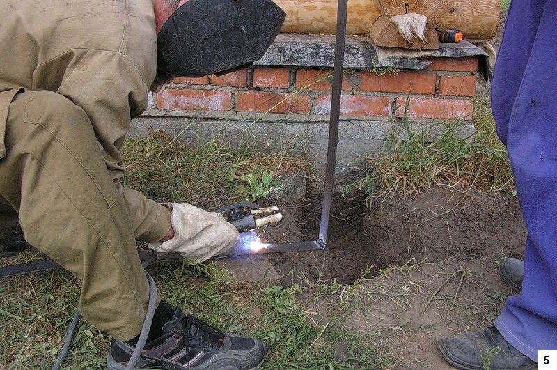
Step 5: mounting the connecting strip from the electrode to the switchboard
- check the resistance with an ohmmeter. If the indicator is less than 4 ohms, you can fill up the trench. If more, we drive in a few more electrodes and connect them to the previous ones. Thereafter, the risk of electric shock from household appliances will be reduced to zero.