home/Electrician/Photo relay for street lighting: criteria for a successful choice and subtleties of installation
Photo relay for street lighting: criteria for a successful choice and subtleties of installation
Technologies in the modern world are constantly evolving. One of the most recent discoveries is advanced developments in the field of outdoor lighting. In addition to economical and bright LED lamps, an important achievement is the photo relay for street lighting. The latest technology belongs to the category of intellectual, since the lamps, thanks to special software, light up and go out without human intervention. The article will tell you in detail about the device.
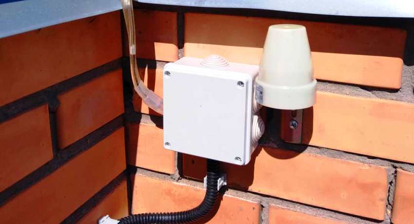
A photo relay is a device for adjusting and turning on street lighting
Photo relay, or street light sensor to turn on the light
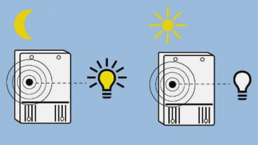
A photo relay is a device for adjusting street lighting. It is used in various places to save energy. The principle of operation of the relay, which is based on the photoelectric effect, is that with a small number of light rays, the contacts are closed. This activates the outdoor sensor. When the illumination rises to the required level, the contacts are automatically opened and, accordingly, the lamps are turned off.
Photo relays are used in different places in order to save energy
The device has many names and definitions. In some technical textbooks it is called a light control switch, in other publications it is called a photosensitive switch. In unofficial vocabulary most often you can hear the phrase "light sensor" or "light sensor", "photosensor". There are also simpler names such as "twilight sensor" or "day / night switch". All these are the names of the same item, which in industrial production is called a photo relay.
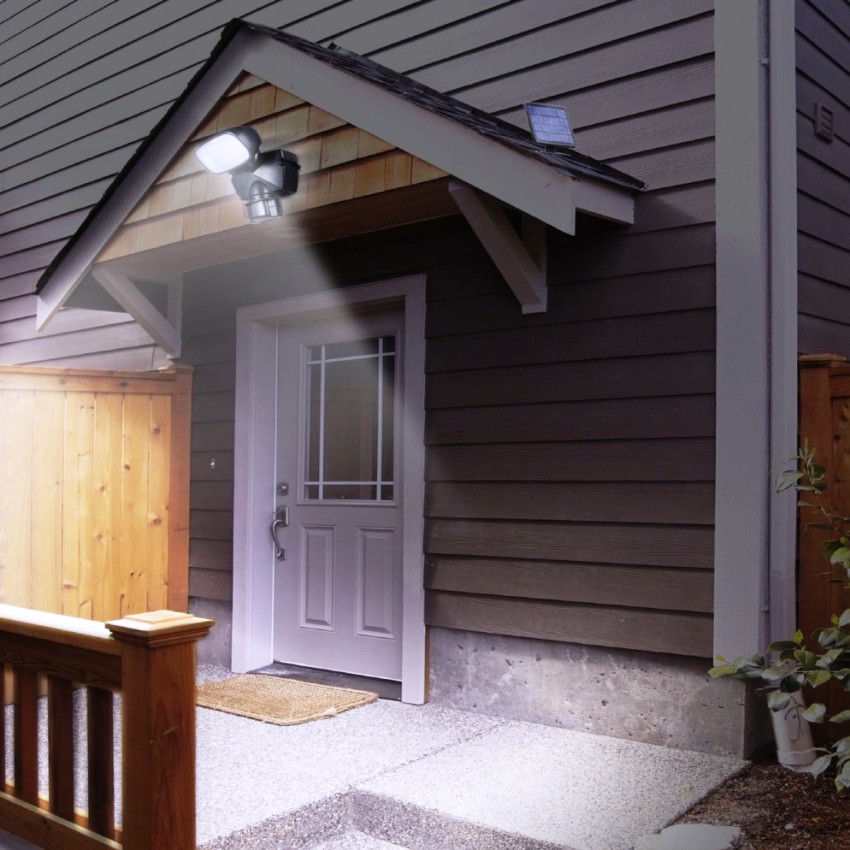
Photo relays are installed at the entrances to houses, in the territories of administrative buildings, in the entrances of apartment buildings, on power poles. Thus, entrances to premises, streets and roads will be constantly illuminated at dusk. In the presence of such a device, the forced switching on and off of lanterns and street lighting lamps on the poles is not required.This will happen automatically, and the cost of electricity will be significantly reduced.
The principle of operation and device of the light sensor for street lighting
The photo relay is based on a photoresistor or phototransistor, which change its parameters with a certain change in illumination. If enough light hits them, then the power supply is open. With the gradual onset of darkness, the photocell begins to react, and at a certain reading specified in the settings, the circuit is closed. The process can take place not only in the evening, but also, for example, in very cloudy weather. When the lighting improves, that is, morning comes (or the clouds and fog dissipate), then the circuit is opened.
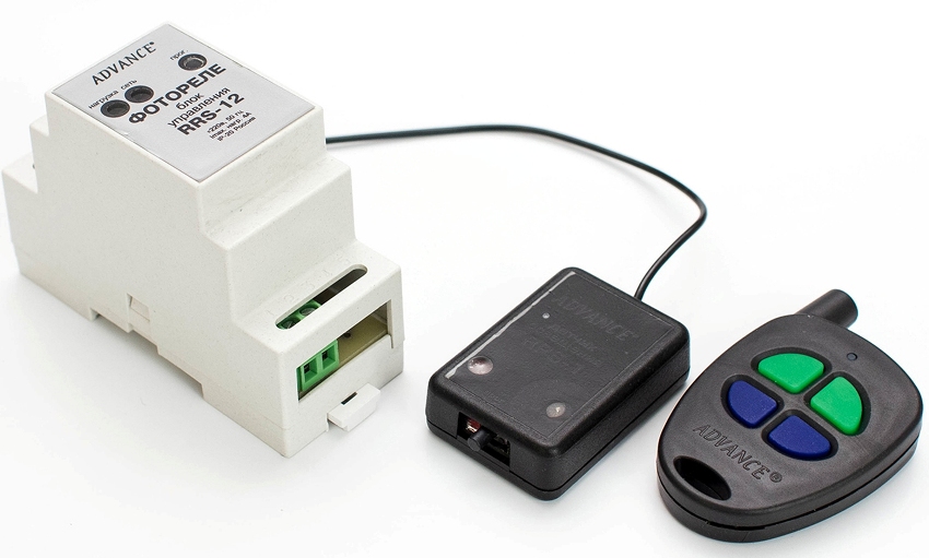
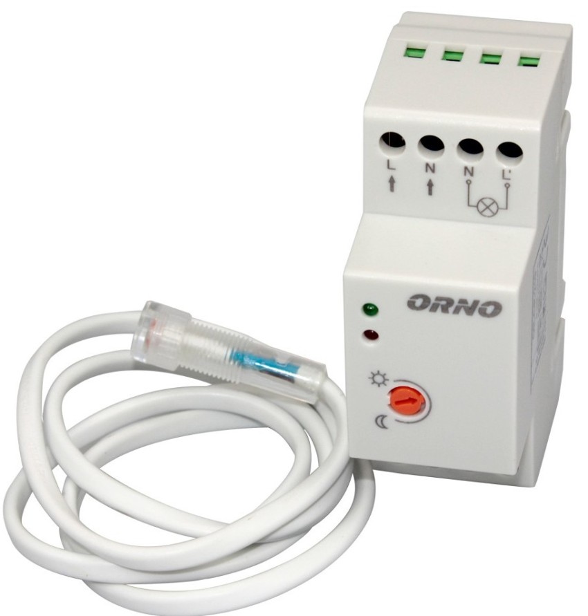
Main unit and remote sensor photo relay for street lighting
Interesting to know!The photo relay device is considered universal, and it can be used for other purposes, for example, for irrigating lawns. To do this, the device is connected to an irrigation system and, thus, the lawn or flower bed will be moistened every night.
When installing street lighting, you need to decide what technical characteristics the photo relay should have. According to this principle, two types of devices are distinguished:
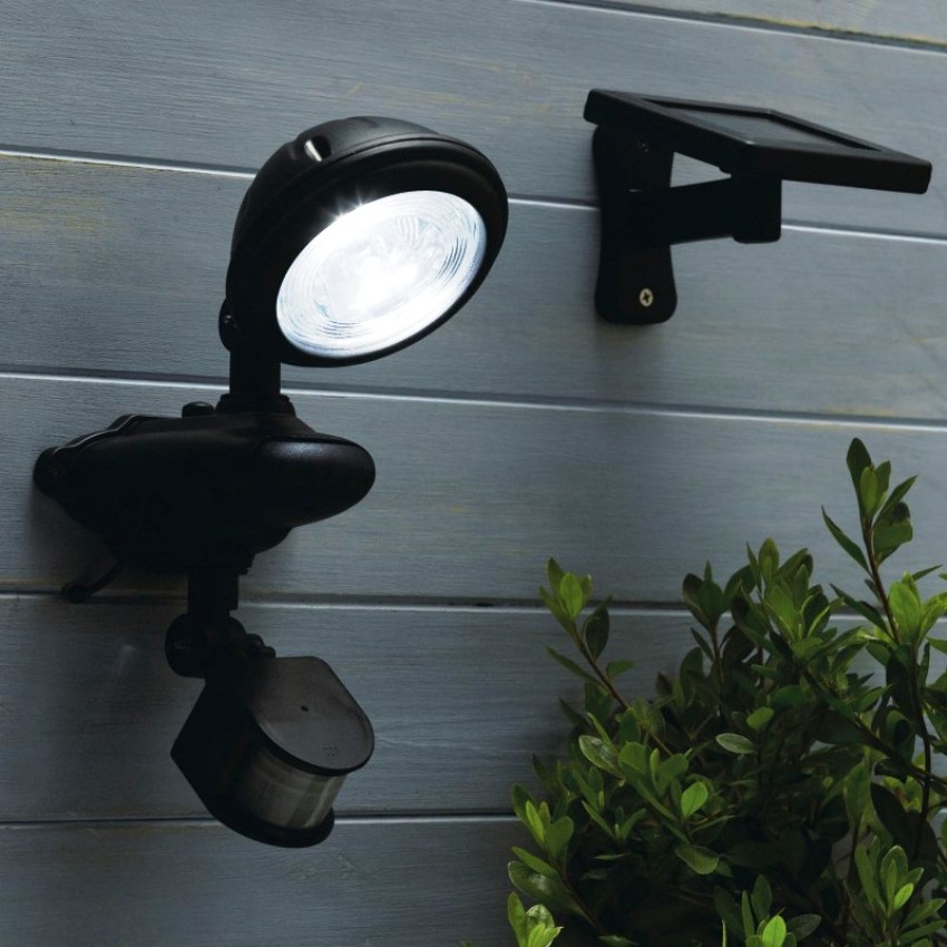
The remote sensor device is small in size, it is easier to provide it with protection from external negative influences and backlight. This device can be placed autonomously, for example, in an electrical room. An example of such a photo relay is a DIN rail model. The built-in sensor should be located in close proximity to the lighting fixture, for example, next to lamps - on street lighting poles. In this case, it is very important to choose such a place that the lamp light does not fall on the photosensor. This option is most often used when installing solar-powered street lighting.
When installing street lighting, you need to decide what technical characteristics the photo relay should have
Performance characteristicsoutdoor light sensor
Having chosen the required type of sensor, it is necessary to determine the technical parameters of the device. The main ones that directly affect the quality of work and the service life of the photo relay are as follows:
Mains voltage. It can be 220 or 12 V - the choice depends on the voltage that provides the street lighting. Twelve-volt light-on sensors are most often used for battery lighting.
Operational mode. It is necessary for the photo relay to work with significant temperature changes, which depends on the climatic conditions in a particular region. Ideally, the appliance should be able to withstand extreme heat and severe frost.
Enclosure protection class. For the installation of street lighting, the level of IP44 and higher is suitable, which ensures the protection of the device from splashing water, dirt and solid particles with a diameter of more than 1 mm. If we are talking about installing a photo relay in a room, then a protection level starting from IP23 is suitable.
Power. The operation of any relay is designed for a certain voltage level of the power load, and the total power of all connected devices must be 20% less than the permissible norm. Thus, it will be possible to reduce the wear rate of the devices and extend their service life.
The photo relay works with significant temperature drops, regardless of climatic conditions
This is the main, but not the final list of the characteristics of the photo relay that must be taken into account when choosing a sensor. A competent approach in this matter will have a positive effect on the performance of the device and extend the period of its operation.
Useful advice! One of the main conditions for the smooth operation of the photo relay is the presence of a stable voltage in the network, which should be 30% higher than this indicator of the device itself.
Light sensor connection options
Almost all devices have an automatic adjustment system that allows you to select a specific operating mode. The peculiarity of this element of the device is that it has to be adjusted manually. To do this, turn the special regulator in the desired direction and select the required option.
The photo relay is used to automate the street lighting system and at the same time save energy
The photo relay can include the following setting controls:
Response threshold. This setting involves increasing or decreasing the sensitivity of the instrument. It is recommended to lower its level in winter, especially in snowy weather, in order to avoid unnecessary reflection of light from snow, as well as in places with bright street lighting, for example, in megacities.
A second delay for turning the device on or off. If you increase the turn-off delay, you will be able to avoid false alarms that occur when a random beam hits the photo relay, for example, the light from the headlights of a car. The switch-on delay will prevent the device from reacting to fleeting blackouts of the device, for example, from clouds or shadows of flying birds.
Illumination range regulator. When connecting a photo relay, using this setting, you can provide the required level of illumination. At its lower limit, the sensor is triggered, turning on the power supply, and, conversely, in the upper values, it turns it off. The range can vary from 2 to 100 lux (2 lux - pitch darkness) or from 20 to 80 lux (in this case 20 lux - deep twilight, when the outlines of objects are barely visible).
Mastering and effective use of the listed settings will help to ensure the most optimal operation of the photo relay, eliminating false alarms, thereby making the lighting more comfortable and the energy consumption as economical as possible.
The photo relay can include many regulatory settings
Choosing the optimal location for the street light sensor
Before connecting the light sensor, you need to decide on the place of its installation, taking into account a number of important points:
if the photosensor is of a remote type, then its location should be in direct reach of daylight;
sources of artificial lighting should be located as far as possible from the sensor, the main thing is that the relay does not react to their switching on or off;
it is desirable to exclude as much as possible the ingress of light from car headlights.
The optimal height of the photo relay installation is from 180 to 200 cm, which will provide the ability to adjust the parameters while standing on the ground, without using stools and ladders.
There are some tricks to help you meet the requirements above. For example, you can protect the photosensor from flashlights by using a large-diameter piece of black plastic pipe 15-20 centimeters long. To this end, it is necessary to saw the pipe at the bottom at an angle of 40-30 ° from the vertical wall so that it looks up.
The location of the photo relay is selected taking into account a number of rules
Useful advice!In order to standardize the assembly of devices for indicating the photo relay on diagrams and drawings, special designations and terms were invented. They need to be known to those who decided to independently install the device.
If the operation of the relay is designed for one lamp, but of high power, then the ideal place would be to place it directly behind the lamp. This is where random light will hit the least. It is much easier to set up the sensor if it is located on the east or west side of the building. The main condition for this is the absence of objects with bright light near. Therefore, in this case, you need to choose the side where the "exposure" is maximally excluded.
Photo relay for street lighting: equipping with additional functions
Both types of photo relay, both with built-in and remote sensors, have their own varieties.The classification of devices is based primarily on their purpose and additional functional equipment. Both types of devices have subspecies.
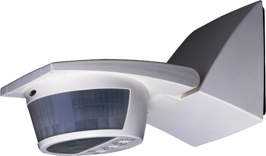
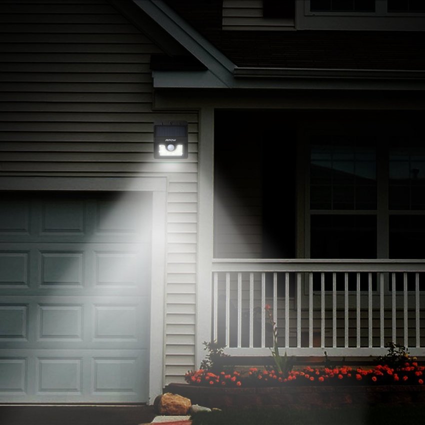
Photo relay with motion sensor. Such a device is installed where lighting is required only during a person's stay, for example, in corridors, in the courtyard of a country house or in a garage. The device reacts to movement and heat emitted by the human body.
A photo relay with a motion sensor is installed where lighting is required only during a person's stay
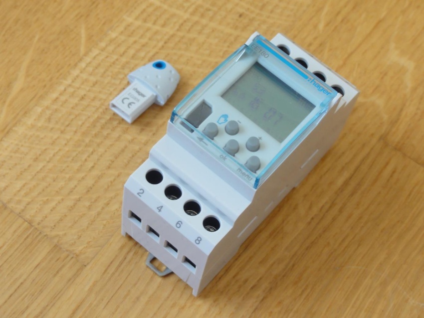
Photo relay with timer. This option is used when illumination is required for a certain time. Users of the device set the desired time when it turns on or off. Accordingly, the device is equipped with a timer for turning on and off the light. Such sensors are especially relevant in decorative illumination of personal plots or buildings.
Astrotimer is not just a photo relay, but a more advanced device, programmed for sunrise or sunset in different climatic zones. It is enough to select a specific time zone in memory. The device will automatically work at the time specified by the program. The price of a photo relay with an astrotimer is much higher, but you do not need to worry about the installation site.
Devices with additional functions are not popular, since the price of a photo relay for street lighting with built-in sensors can be twice as high as the cost of a conventional light-responding device. Therefore, to provide additional functions, it is not at all necessary to purchase an expensive multi-photo relay, it is enough to buy a conventional device and additionally install motion sensors or timers.
Astrotimer is a more advanced device programmed for sunrise or sunset.
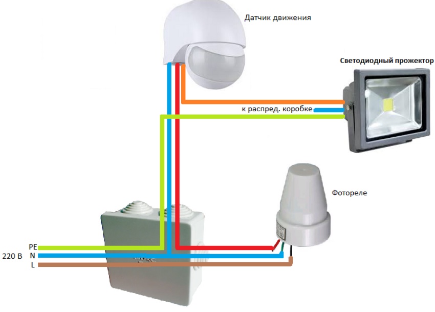
Photo relay connection diagrams for street lighting
The main function of the photo relay is to supply power at nightfall and turn it off at dawn. Thus, it is a circuit breaker that operates without human intervention. The photosensitive element plays the role of the shutdown button. The connection diagram of the photo relay is similar: a phase is applied to the device, it is interrupted at the outputs, and, if necessary, the circuit is closed, as a result of which voltage is supplied to lamps or floodlights.
Types, technological features of devices, specifics of the installation. Value for money.
To ensure the operation of the photo relay, power is also required, therefore, zero is connected to certain contacts. Since the lighting is supposed to be in an open area, there is a need for a ground connection.
It is important to correctly connect the conductors coming out of the housing of the regulator itself with the lamp and the network
Useful advice! To provide additional functions, you can purchase a photo relay with motion sensors or timers. However, two separate sensors, for example, light and motion, are cheaper to buy and maintain. In addition, it will be easier to replace a part in one of the two devices than to repair all the photo relay in the complex.
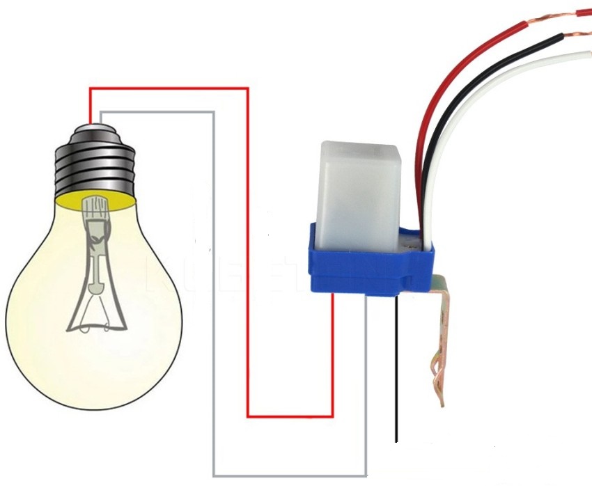
Unfortunately, there is no universal wiring diagram that would fit all types of photo relays, but certain points are characteristic of all operations. They must be taken into account, especially in the case of installing a photo relay with your own hands.
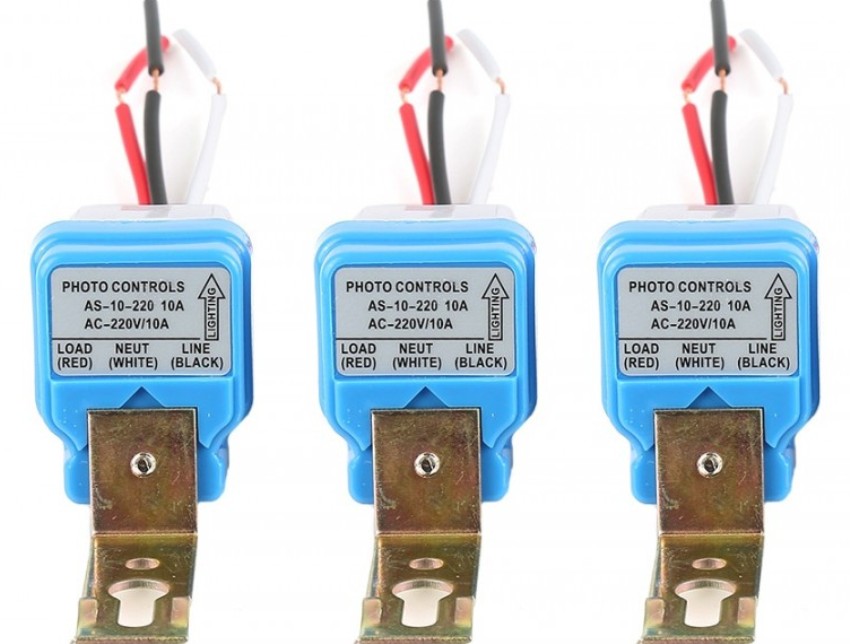
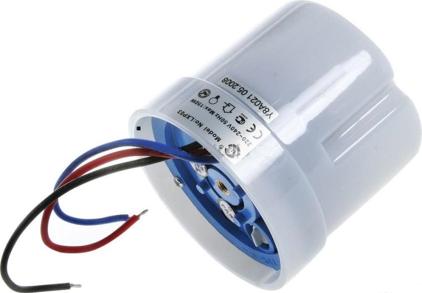
In almost all models, the relay at the output has three multi-colored wires that correspond to the following designations:
black - phase;
green - zero;
red - the phase switching to the light source.
To provide additional functions, you can purchase a photo relay with motion sensors or timers
Step-by-step instructions for connecting a photo relay for street lighting
The instruction below will tell you how to connect the photo relay in stages, quickly and correctly:
Pre-installation of the switchboard. Usually it is mounted on a wall, and conductors are connected in it.
Connecting the photo relay according to the diagram, which is in the technical documentation attached to the device itself. Usually a bracket is used as a fastener. It is installed in a place where the direct rays of the sun will fall on the relay, but other light sources are isolated.
Correction of the system using a regulator, that is, the choice of parameters for the response of the device to specific conditions of changing illumination.
The regulator is installed on the outside of the device with the appropriate technical characteristics: sensitivity range - 5-10 lm; power - 1-3 kW, threshold of permissible current - 10A.
If the device is mounted in the middle of an electrical panel with a complex structure, where the sun's rays do not penetrate, then the relay and the switch are installed separately from each other. Connect the parts of the device to each other with special cables.
The photo relay is connected according to the diagram that is in the technical documentation attached to the device itself
When installing street lighting, it is recommended to follow these rules:
It is better to place a device with an external photocell in such a way as to exclude direct light from the installed luminaire. Otherwise, the device will not work properly.
To check whether the circuit is correctly connected or not, it is necessary to connect the starter to the mains. The result will be clear when the lamp is triggered.
Nuances in the light sensor connection diagrams
The fact that the photo relay is selected taking into account the expected load may affect the cost of the product: depending on the power, the price increases. Therefore, in order to save money, it is possible to provide power supply not through the photosensor, but through a magnetic starter. This is a special device designed for frequent on / off operation. The use of the trigger allows you to connect power using a photosensitive element with a minimum load.
Thus, in fact, only the magnetic starter is switched on, therefore only the power consumed by it is taken into account. But already at the terminals of the magnetic starter, the use of a more powerful load is allowed.
In order to save money, you can provide power not through the photosensor, but through a magnetic starter
Useful advice!Before installing and configuring the device, it is recommended to carefully study the lighting connection diagram that is attached to the device. The document clearly and visually depicts all the wires of the photo relay, and also shows where they need to be connected.
In the event that, in addition to the day / night sensor, it is necessary to connect devices with additional functions, for example, a timer or a motion sensor, then they are installed after the photo relay is installed. In this case, the order of priority of additional devices is not important.
If the function of a timer or motion sensor is provided in the structure of the device, but it is not needed in a specific case, then these devices are simply excluded from the general circuit, that is, they are not connected to wires. In this case, if necessary, these elements of the device can be connected.
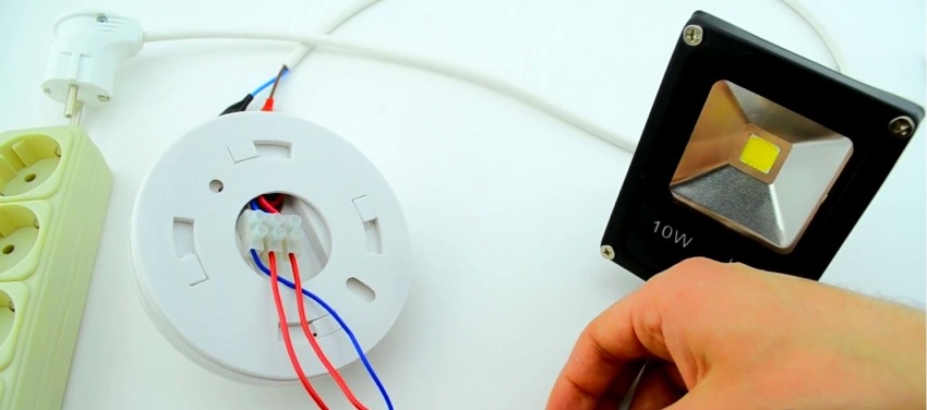
Setting up street lighting for a country house
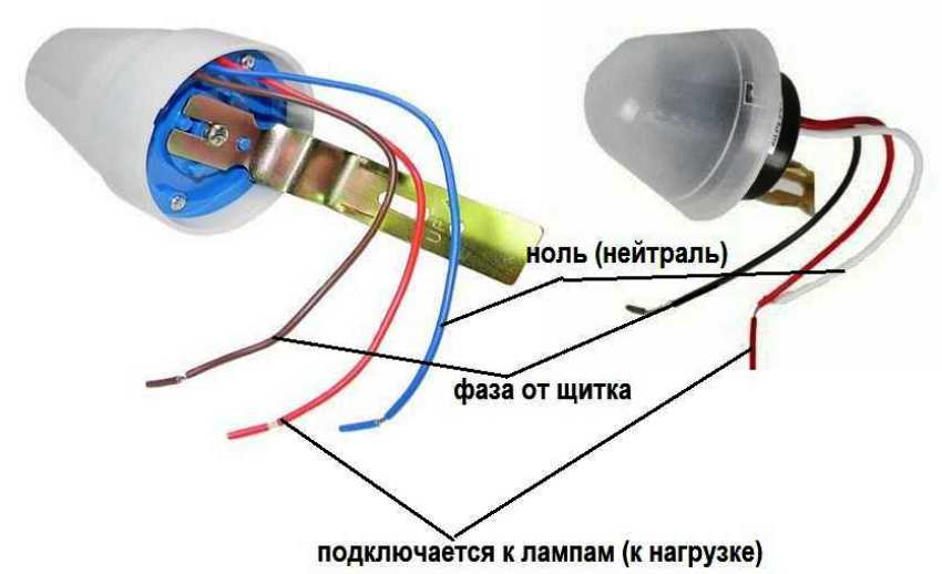
After the photo relay has been connected, it is necessary to configure it, taking into account a number of nuances. As mentioned earlier, a photo relay with a built-in photosensor has three wires at the exit from the case. They are connected in this way:
red, responsible for electrical loading, goes directly to the lantern, lamp or spotlight;
After connecting the photo relay, it is necessary to configure it, taking into account a number of nuances
a brown or black wire is connected to the phase coming from the shield;
the blue wiring is connected to zero on the shield body.
An optional but important point in ensuring safety is the ground connection. For this purpose, a separate wire is connected to the terminal on the body. In this case, the cross-section of the wire must be selected in accordance with the power of the expected load of the photo relay. The wiring diagram will tell you how to do it correctly.
The device is configured after installation. To do this, you need to wait for the moment of natural light, when it is desirable to turn on the lamps. Adjust the device by turning the tuning wheel. You need to twist until the lamp turns on.
It should be noted that the procedure for connecting a relay with a remote sensor is slightly different from connecting a device with a built-in photocell. Here, the phase is connected to terminal A1 (L), which is located at the top of the device, then zero is brought to terminal A2 (N). From the output, depending on the location of the wire, the phase is fed to the lights.
There are three wires on the photo relay with a built-in photosensor at the exit from the case
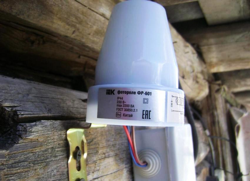
Characteristics and connection features of individual sensor models: photo relay FR 601 and FR 602
The modern domestic market is represented by a wide range of photosensor models designed for different types and lighting conditions, assuming different lamp powers and the presence of additional functions.
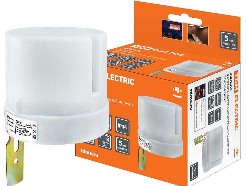
The most popular among standard single-phase models are the FR-601 sensor and its more advanced analogue of the FR-602 photo relay. The manufacturer of the devices is the IEK company. Both types of sensors are characterized by reliability and ease of connection. The differences between the models are insignificant, they operate on a current of the same voltage and frequency, and the power consumption is 0.5 W. Outwardly, the devices are completely identical.
Useful advice! To connect several lights at the same time, you need to purchase a special controller. This device will receive a signal that controls the lighting.
The only difference is the maximum cross-section of the conductors to be connected. Model FR-601 is designed for 1.5 mm², and FR-602 - for 2.5 mm². Accordingly, they have different rated load currents. For the FR-601 photo relay, it is 10A, for the FR-602 - 20 A. Both devices have a built-in photocell, and the adjustment is permissible in the range from 0 to 50 lux with an interval of 5 lux.
The most popular among the standard single-phase models are the FR-601 sensor.
Such devices can be built even at home. The main difference between a homemade device and a factory IEK photo relay will be in the absence of appropriate protection. This level for serial models is IP44, which means protection against dust and moisture. The connection diagram of the photo relay FR 601 and FR-602 is standard and simple. The products serve for a long time and withstand the influence of temperatures of a wide range.
Among the analogs of this device is the FR-75A model - a photo relay, the circuit of which is more complicated for making at home. The device is less stable and less durable in practical use.
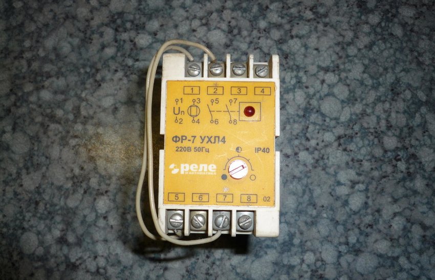
High-power photosensitive sensors: photo relay FR-7 and FR-7E
The models discussed above are ideal for ensuring the operation of street lamps on the territory of a summer cottage or in the courtyard of a private house. More powerful models are used to adjust the lighting on city streets and on roads. These include FR-7 and FR-7e, which can operate in a 220 V AC network with a voltage of up to 5 amperes. The adjustment of these devices should be carried out by specialists, since a connection of a range equal to 10 lux is required.
Among the disadvantages of the FR-7E photo relay, like its predecessor FR-7, it should be noted the high level of power consumption. Also, the devices do not have the required level of protection IP40, which protects against the negative effects of moisture.In addition, the models do not have a trim resistor on the outer panel protected, the terminals are of the open type.
The main disadvantage of the FR-7 photo relay is the high level of power consumption.
Considering individual photosensors, it is necessary to mention the popular model of the FRL-11 photo relay with an external photosensitive element. The device operates in a wide range of illumination (2-100 lux). The photosensor is equipped with IP65 protection, which allows it to be installed outdoors, and at a decent distance from the relay. The devices are used to control the lighting of large objects: roads, parking lots, train stations, parks, etc.
Photorelay FR-16A belongs to the category of the most powerful models with a built-in photocell. The light sensor can be configured to operate in a specific light level. The device requires a switching current of 16 A to operate, and the device's load power is 2.5 kW.
Installation of a photo relay in street lighting eliminates human intervention in the process of adjusting the operation of lighting electrical devices, which allows you to significantly save on electricity consumption. When buying equipment, the consumer should focus on the parameters of the device, choosing a model for specific purposes with the required degree of load. During connection, you must strictly follow the instructions and the attached diagram, and during operation - the manufacturer's recommendations.