From this article, you can find out what an electric multimeter is: a tester that can measure current, AC and DC voltage and resistance. Let's consider which devices have additional functions, such as measuring the gain of a transistor, testing diodes, continuity of an electrical circuit, measuring the frequency of an electrical signal, temperature, parameters of capacitors, inductance of coils.

The multimeter is used to take a fairly wide range of indicators of electrical complexes
Content
Electrical multimeter: tester for measuring electrical characteristics
To measure electrical indicators, universal multimeters (testers), the current clamp DT 266, which is a portable compact model of the device. All multimeters have a similar design with the exception of some distinctive features. A typical tester consists of:
- LCD display;

Modern testers combine the functions of a voltmeter, ohmmeter, ammeter, frequency meter, as well as an inductance and capacitance meter
- rotary switch of measurement modes;
- three connectors for connecting probes;
- sockets for connecting a transistor;
- on / off buttons.
On the case of a digital multimeter (tester) there is a scale for the designation of the measured values and their maximum values. By turning the switch, you can select one of them:
- DCV - DC voltage measurement;
- ACV - AC voltage measurement;
- Ω - resistance measurement;
- DCA - DC current measurement;
- HFE - measurement of transistor parameters;
- diode sign - check or continuity of diodes

Scale of designation of measured values and their maximum values
The device is equipped with several sockets for connecting red and black probes. The styli are included, but they are often of poor quality. If they fail, you can make probes for a multimeter with your own hands, for example, from fountain pen cases and dart tips. To measure the values, you must connect them correctly, otherwise you can damage the multimeter.The black probe should be connected to the COM jack, and the red one should be connected to the 10A connector to measure current strength over 200 mA, and to the VAΩ jack when measuring voltage, resistance, current up to 200 mA, and when dialing is performed.
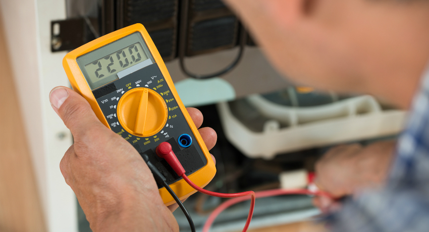
How to use a multimeter correctly
Before you start measuring electrical quantities, you should check the device. It must be connected to an outlet in parallel with another tester or voltmeter and check the readings. To check the accuracy of the resistance measurement, take the device with the marking and compare it with the reading of the tester. To make sure that the current indicator is measured accurately, it is worth taking alternate measurements of the same load with this device and an ammeter.
Using the DT 832 multimeter as an example, the instruction manual of which contains a detailed description of all manipulations with the device, we will consider the main modes of operation of the device.
The resistance scale can be used for such purposes as ringing a transformer with a multimeter, determining the resistance of a resistor, identifying faulty elements, which show undervoltage, reverse resistance of diodes, resistance of a heating element.

When using a multitester, it is very important to follow all safety rules
To measure resistance, you must set the rotary switch to the appropriate Ω sector. If an approximate value is not known, the switch is set to the lowest value that corresponds to 200 ohms. If the display shows "1", it means that the resistance is higher, so you need to go to the next level. Take measurements until correct information is obtained.
Note! It should be remembered that before taking a resistance measurement, you should make sure that there is no power in the network. Otherwise, the device will produce deliberately false values.
To measure AC voltage, point the switch to the V ~ or ACV sector, which consists of two positions 200 V and 750 V. Measurements start from the larger value. If the result is small, then for a more accurate measurement it is worth moving to a low position. The black probe is connected to the COM connector, and the red one to VAΩ. When measuring this indicator, the polarity is not necessary.
To measure DC voltage, the multimeter switch is installed in the V or DCV sector, where the scale is divided into 5 ranges. Measurement should be started from the highest value of 1000 V, and gradually reduced until the correct result is obtained. If you do not follow this rule, the device may be damaged.

The scale of designations of the measured quantities has the same values in all models of multimeters
DC current measurement should be done with extreme care and accuracy. To do this, you must set the switch to the desired DCA sector. Now you should connect the probes correctly. Black is still plugged into the COM connector, and red should be set to VAΩ when the estimated current is less than 200mA. If the current is higher than this indicator, then the probe is set at 10A. If you mix up the positions, you can burn the multimeter.
You should start measuring the current strength with a multimeter from the maximum value of the measurement threshold, gradually lowering it until the required value is obtained.
Important! For current measurements, the multimeter should be connected to the circuit in series, and for resistance and voltage - in parallel.
Temperature measurement with a multimeter is performed using a thermocouple, which is connected to the device instead of probes.

To measure values with a multimeter, probes, thermocouples or clamps are used
When working with electrical engineering, it is sometimes necessary to determine the inductance. Finding a tester with this function is quite difficult.For this you need to use a special attachment. A digital tester with a voltage measurement accuracy threshold of 200 mV is suitable as such an element for measuring inductance with a multimeter.
How to ring the wires with a multimeter
When it is necessary to determine the health of the equipment or the health of the wiring, the first thing to do is ring the cables and wires with a tester. It will immediately identify a possible break in the circuit, its resistance and the presence of a short circuit.
Useful advice! It is not necessary to use a model with this function for wire continuity. An inexpensive multimeter with minimal capabilities is suitable for this.
First you need to set the switch to the diode icon. The red probe should be installed in the Ω connector, the black one - COM. Further, to check the device, it is necessary to close the ends of the measuring probes together. A characteristic signal should ring. Now you can start dialing the wire. To do this, touch the bare sections of the cable or wire with the measuring probes. An audible signal indicates the integrity of the wire. In this case, the screen will display the resistance value or "0". If there is no sound signal, and the display shows the value "1", then the tested wire is broken.

If the polarity is wrong, nothing will happen, but before the result the display will show "-"
Next, let's look at how to ring a multi-core cable with a multimeter. To do this, each end must be stripped and straightened. Now you need to check for a short circuit in each core. Here, the sound signal symbolizes the presence of a short circuit between the cores. This is especially important when working with high voltages.
Now you need to check the integrity of all the veins. The conductors of one end of the cable are twisted together, and at the other end, each is checked by the device. If the sound signal is absent at least once, the integrity of the conductor is broken.
Measuring the capacitance of a capacitor with a multimeter
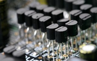
The most common reason for the breakdown of electronic equipment is the malfunction of the capacitors that are part of the board. To identify the weak link, you need to ring each of them with a multimeter.

Capacitor breakage can be easily identified with an electrical multimeter.
Before you check the capacitance of the capacitor with a multimeter, you must completely discharge it, otherwise it can damage the measuring device. To discharge a low-voltage device, it is necessary to short-circuit its terminals, and for a high-voltage capacitor with a large capacity, a 5-10 kΩ resistor should be used, which is connected to the device.
A serviceable capacitor has a capacity of at least 0.25 μFarad. Before checking the capacitance of the capacitor with a multimeter, the device should be set in the appropriate measurement mode to the required limit. If the tester is equipped with special sockets, insert a capacitor into them.
How to check a capacitor with a multimeter without removing it from the board? To do this, connect them to the measuring device and touch the capacitor leads. The polarity must be strictly observed here. Otherwise, the device will immediately fail. The multimeter will display the capacitance value, which should be close to the nominal. If not, the capacitor is defective.

You can check the performance of the capacitor with a multimeter even without the capacitance measurement function
Important! Please remember that capacitor manufacturers always check the minus pin on the device.
How to ring a capacitor with a multimeter if there is no function for measuring its capacitance? To do this, it is necessary to put the device into the resistance measurement mode and touch the probes to the corresponding polarity of the terminals.The tester will display a value that will increase. This is due to the fact that the multimeter, in contact with the capacitor, charges it. After a while, the screen will display "1", which indicates that the device is in good working order.
If at the beginning of the check the number "1" appeared on the screen, it means that there was an open circuit in the capacitor and it is already faulty. If "0" appears, a short circuit has occurred inside the device.
A more detailed course of measurements can be viewed in the video - how to check a capacitor with a multimeter.
Related article:
Multimeter: which is the best to choose a device for use at home
Specific features of the device. Varieties of testers. How to use the device correctly. Rating of the most popular models.
How to ring resistors with a multimeter
A resistor is an electronic element with a variable or specific electrical resistance. Before you ring the resistor with a multimeter, you must visually inspect it for chips and cracks on the device case. If there is no visible damage, then you should start checking the element. To do this, you must use a schematic diagram, on the basis of which measurements are taken at control points, where the required values of the quantities are indicated.
The most common way to test a multimeter with a resistor is to measure the resistance, which should be close to nominal. For this, the tester switch is set to the appropriate position. The red probe is connected to the VΩmA connector, and the black one is connected to COM.

A multifunction tester is also used to test resistors.
Before ringing the resistor, it is worth identifying the good condition of its wires. They are closed together. The device should display "0". Now you can proceed to measuring the resistance of the resistor. If the display shows "1", the resistor is defective. If another value is displayed, it is compared with the nominal value, taking into account the tolerance. The resistor is good if the values match.
How to check a resistor with a multimeter without removing it from the board? To do this, you can use the dialing mode. If the element is OK, a characteristic signal will sound.
The use of a multimeter in everyday life
With the help of a tester, you can diagnose many elements of electrical appliances and thereby identify a malfunction.
Before you ring the heating element with a multimeter, you should find out its resistance, which will be compared with the reading of the tester. To do this, you must use the formula R = U2 / P, where U is the supplied voltage, P is the power, which is indicated on the device case.

A popular problem with household appliances is the failure of the heating element, which can be checked using a multimeter.
To measure, set the switch to the required range for resistance measurement. Attach the multimeter probes to the housing of the household appliance and to the output contacts of the heating element in turn. If the display shows a value close to that obtained from the formula, then the heater is working properly. A value of "0" indicates a short circuit inside the coil, and an infinite value or “1” indicates that the coil is broken.
The question often arises: how to ring the electric motor of a household appliance with a multimeter? Since there are several types of engines, the performance check of the unit will differ.
Before checking the electric motor with a multimeter, it is necessary to make its external inspection, touch your hands to metal surfaces.
The device must be completely de-energized before testing. Set the tester to ohmmeter mode by switching to the maximum measurement range. How to work with a multimeter, the video in the article clearly displays the sequence of measurements to check the engine's performance.

When measuring indicators, it is worth considering the errors of the multimeter
Many lighting fixtures today are equipped with progressive light sources, such as LEDs, which can periodically fail. It is then that an important task arises, how to check the LED with a multimeter. To do this, it is necessary to use a tester with a dialing mode, in which the efficiency of the diodes is checked. The polarity of the LED must be observed here.
The red probe of the device connects to the anode, and the black one to the cathode. If everything is done correctly, the working LED should start to glow. However, it should be borne in mind that when working in continuous mode, the multimeter has a low current indicator, so the diode may not respond. Here you should reduce the lighting in order to clearly see the glow of the diode. Also, the value displayed on the tester display, which differs from 1, indicates the good condition of the element.
Useful advice! Here, at the same time, you can check the power of the LED with a multimeter, calculating this parameter based on the results obtained.

Digital instruments have the function of fixing readings, which is convenient when checking several indicators
Using the tester, you can identify two defects in the operation of a simple voltage and current converter. Before you check the transformer with a multimeter, you need to know the conclusions of all its windings. Then, using a measuring device, ring each winding of the device in ohmmeter mode. If the tester displays 1, this indicates a broken winding.
To detect a short circuit, touch one probe of the tester to the winding terminal, with the other, alternately connect to the terminals of other windings and the case. There should be no short circuit here.
How to check the battery capacity with a multimeter
Rechargeable batteries are used to store and power consumers with electrical energy during autonomous operation. A multimeter can check the operating voltage, operating current, internal resistance, EMF and battery leakage current. The most common question is how to check the battery charging with a multimeter.

Using a multi-tester, you can check the battery charge
To do this, ensure that the battery is fully charged. Further, with the help of a powerful consumer, a load is created on the battery by connecting the battery, tester and consumer in series. The current is measured. The battery voltage needs to be measured periodically. As soon as this value starts to decrease, the start time of the battery discharge is recorded. Now the total time that has passed since the start of the test is multiplied by the load current. The value obtained corresponds to the capacity of the battery.
The result obtained after checking the battery with a multimeter should be compared with the passport data. If the value is lower than the nominal, the device is not suitable for further operation.
When using many household appliances, some users are interested in how to check the capacity of an 18650 battery with a multimeter. First, you need to know the nominal cell capacity, the value of which is usually written on the case.

For dialing and troubleshooting, the multimeter has a built-in function for generating a test signal
Considering the question of how to measure the battery capacity with a multimeter, it is necessary to understand the process technology. The meter is set to DC current measurement in the 10 MA range. Further, the red probe is connected to the positive terminal of the battery, and the black one to the negative one. The screen should display a value that is close to the nominal. Then the element is suitable for further work.
After we have checked the battery capacity with a multimeter, according to the value obtained on the device, we can talk about the further fate of the element.If the result is slightly below the nominal, the battery can be used for more powerful equipment, for example, for a clock, flashlight. If the value is close to 1 A, the element is useful for ensuring the operation of the remote control.
If the question is how to check the battery capacity of the phone with a multimeter, remember that the tester will only show an approximate value. For a more accurate diagnosis, use a computer program or a special charger.

A multimeter cannot measure the battery capacity of the phone, but only an approximate value of consumption in amperes
Car Multimeter Application
Many car owners often ask themselves the question: how to check the car battery with a multimeter with the engine running? For this, the tester is switched to the voltage measurement mode. Observing the polarity, the measuring device is connected to the battery. If the display reads 13.5-14 V, this indicates the normal operating condition of the power supply. If the reading is above 14.2 V, it is a low battery indication.
Now let's move on to the question of how to check the battery charge with a multimeter when the engine is not running. The measuring principle remains the same as when the engine is running. Normal operation of the battery should correspond to the obtained value, which is in the range of 12.5-13 V. If the value is below 12 V, this indicates that the unit is completely discharged.
One of the important parts of any car is the mass air flow sensor. How to check the flow meter with a multimeter is described below. To do this, you need to understand the design of the sensor and strictly follow the instructions.
It is not necessary to use the services of a car service to check the operation of the mass air flow sensor. Saving money and time, you can check the DMRV with a multimeter. First you need to know the pinout of the contact group. It is not necessary to remove the sensor from the installation site.

A multimeter is a necessary parting in the car owner's arsenal, which will help to save money on car service
The tester is set to the DC current measurement mode up to 2 V. The DMRV sensor is checked with a multimeter in a clear sequence. The red probe touches the yellow wire, which is responsible for supplying the signal coming from the ECU. The black probe connects to the green ground wire. Turning the ignition key without starting the car, you need to look at the readings of the device.
The test of the VAZ-2114 DMRV with a multimeter was successful if the device display shows a value of no more than 1.02 V. The sensor does not work if the tester displays a reading exceeding 1.05 V.
Note! In order to check how it works with a DMRV multimeter on a VAZ 2110, you must complete all the above steps.
Before checking the camshaft sensor with a multimeter, you must turn off the ignition. Then disconnect all wires from the device. Switch the tester to voltage measurement mode. Connect the earth of the tester to the engine ground. The measurement result should correspond to the voltage characteristic of the battery terminals. If the readings differ, the power circuit of the device is out of order. After, in a similar way, you should measure the voltage at the sensor ground. It should be equal to 0.

You can check the car battery with a multimeter both when the engine is running and when the engine is not running.
Now connect one wire of the multimeter to the strong terminal of the sensor, and connect the other to the input of the control system. Crank the engine with the starter. If the screen displays 0.4-5 V, the sensor is working.
How to check the knock sensor with a multimeter? The device is set to the voltage measurement position at 200 MV. The probes are connected to the contacts. Now you should hit the device with a hard object.If on the device, depending on the impact, the voltage readings increase to 40 MV, the sensor is faulty.
Next, let's look at how to ring the ignition coil with a multimeter. First you need to make sure that the primary winding is in good condition. To do this, set the device to the resistance measurement mode and connect the probes to the contacts "+" and "-". If the display shows a value in the range of 0.4-2 Ohm, the coil is OK. The number 0 indicates a short circuit. If infinity is displayed, an open circuit has occurred.
The second step in solving the question of how to check the ignition coil with a multimeter is ringing the secondary winding of the device. To do this, you need to connect the multimeter probes to the output from the high voltage wire and to the "+" contact. If the coil is equipped with a plate-type core, the resistance will be 6-8 kΩ, for another type it will be 15 kΩ.

You can check the ignition coil with a multimeter by ringing the primary and secondary windings of the device
A more detailed course of measurements can be viewed in the video "How to check the ignition coil with a multimeter."
Generator check
The performance of the car ignition system is provided by two devices that work in pairs: a generator and a storage battery. Violation of the normal operating condition, one of them will lead to a decrease in the performance of the entire unit.
Before checking the generator with a multimeter, it should be visually inspected. Then you should start testing the relay regulator, which maintains a constant voltage of the car. For this, the tester is set to constant voltage mode in the range of 50 V. Using probes of the corresponding polarity, the voltage at the generator input contacts is measured. It should be between 14-14.2 V.

The generator and the battery are paired, therefore two devices must be checked
If no malfunction is found, you should go to the question of how to check the diode bridge with a multimeter. To do this, you need to disassemble the generator housing and check it.
If the diode bridge is in good condition, the generator rotor should be checked. For this, it is necessary to switch the tester to the resistance measurement mode and check it on the slip rings of the field winding. The value should not be too large.
Useful advice! If a short circuit or an open circuit is found during measurements, contact a specialist for help.
The last step is to carry out a continuity test with a stator multimeter for the absence of a short circuit in the windings. The resistance on the device should be close to 1.

The latest generation multimeters are equipped with the function of sending data to a smartphone, but the cost of such a device is quite high
How to ring a diode bridge with a multimeter
In electronics, diode bridges are often used in one package. You can find out their performance or identify damage using a conventional tester.
Before ringing the diode bridge, the multimeter is set to the diode or continuity test mode. The check is carried out in live connection. The red probe is connected to the negative terminal, and the black one to the terminal marked AC. This measures the threshold voltage, which for silicon diodes is 400-1000 mV.
Useful advice! To 100% make sure that the diode bridge is in good condition, the check occurs in reverse connection. The black probe is connected to the negative terminal, and the red one to the positive terminal. The multimeter should display a value of "1". This says that there is a lot of resistance in the P-N junction, and the diodes do not pass current.
In this way, all diodes of the bridge are checked. If, during the continuity of the diodes, zero resistance appears on the display of the multimeter or the device emits a signal, this indicates a punctured element inside the diode bridge.When checking in reverse connection, the screen will also display "1". However, if, during direct and reverse switching on, a unit is displayed on the device display, this indicates an open circuit when the diode does not conduct current.

The use of a multimeter when checking the performance or damage of a diode bridge
Before using the measuring device, it is necessary to study in detail the instructions "How to use a multimeter", where all possible manipulations with the tester are described in detail. By strictly following the recommendations, you can carry out all the necessary measurements that will not damage the device and make its operation safe.